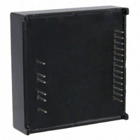
SPMD150STP STMicroelectronics, SPMD150STP Datasheet - Page 11

SPMD150STP
Manufacturer Part Number
SPMD150STP
Description
MOD STEPPER MOTOR DRV 1.5A BIPO
Manufacturer
STMicroelectronics
Type
Motor / Motion Controllers & Driversr
Specifications of SPMD150STP
Motor Type
Stepper, Bipolar
Number Of Motors
1
Current - Output
1.5A
Transistor Type
MOSFET
Termination Style
PC Pin
Product
Stepper Motor Controllers / Drivers
Operating Supply Voltage
50 V
Supply Current
1.5 A
Mounting Style
SMD/SMT
Lead Free Status / RoHS Status
Lead free / RoHS Compliant
Other names
497-10065
Available stocks
Company
Part Number
Manufacturer
Quantity
Price
SPMD150STP
4
4.1
4.2
Function description and application information
SPMD150STP can be seen divided in several main blocks (see
●
●
●
●
●
●
Power stage
STMD150STP integrates two independent MOSFET full bridges, with intrinsic fast
freewheeling diodes. Switching patterns are generated by the phase sequence generator
and by the PWM current controller.
The power MOSFET cross conduction in one bridge leg, is avoided introducing a dead time
(t
VS (pin19) and GND2 (pin14) must be connected to the supply voltage, which can range
from 10 V to 42 V.
Logic interface
Logic interface connects the external logic signal to the proper internal blocks.
RESET (pin3), CLOCK (pin4), CW/CCW (pin5), CONTROL (pin9) and HALF/FULL (pin10)
have a 10kΩ pull-up resistor to VSS (pin1), in order to prevent floating pins;
VSS can be connected to 3.3 V or 5 V, allowing the interface with the most popular
microcontroller. The internal structure is shown in
EN (pin8) has identical input structure, with the exception that the MOSFET drain of the
over-current and thermal protection is also connected to this pin (see
Due to this connection some care needs to be taken in driving this pin.
Inside the module a 100 kΩ resistor and a 100 nF capacitor is provided, an open collector
driving is therefore the suggested solution.
DT
= 1 μs typical), between FETs switch off and the switch on.
Power stage, to drive the motor windings
Logic interface, to interface the external signals to the internal circuitry
PWM current controller, to fix and control the current flowing in the motor phase
windings
Decay control block, to control the phase current decay mode
Phase sequence generator, to generate the motor phases driving sequence
Protection block, performing over current protectionand thermal shut-down to protect
the power bridges
Doc ID 17160 Rev 1
Function description and application information
Figure
8.
Figure
Figure
1):
9).
11/23


