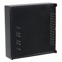
SPMD150STP STMicroelectronics, SPMD150STP Datasheet - Page 12

SPMD150STP
Manufacturer Part Number
SPMD150STP
Description
MOD STEPPER MOTOR DRV 1.5A BIPO
Manufacturer
STMicroelectronics
Type
Motor / Motion Controllers & Driversr
Specifications of SPMD150STP
Motor Type
Stepper, Bipolar
Number Of Motors
1
Current - Output
1.5A
Transistor Type
MOSFET
Termination Style
PC Pin
Product
Stepper Motor Controllers / Drivers
Operating Supply Voltage
50 V
Supply Current
1.5 A
Mounting Style
SMD/SMT
Lead Free Status / RoHS Status
Lead free / RoHS Compliant
Other names
497-10065
Available stocks
Company
Part Number
Manufacturer
Quantity
Price
Function description and application information
4.3
12/23
Figure 8.
Figure 9.
PWM current controller
The control block is composed by a constant Off-time PWM current controller for both two
bridges. The current control circuit senses the bridge current, by sensing the voltage drop
across a sense resistor connected between the source of the two lower power MOSFETs
and ground. As the current in the motor buildup, the voltage across the sense resistor
increases proportionally. When the voltage on the sense resistor becomes greater than the
voltage at the reference inputs VREFA (pin6) or VREFB (pin11), the sense comparator
triggers a mono-stable circuit, switching the bridge off.
The bridge MOSFETs remain off for the time set by pin RCA (pin7) or RCB (pin12);
during this Off-time (see
circulates as defined by the selected decay mode, described in the next section. When the
mono-stable circuit times out, the bridge will turn on again. Since the internal dead time t
used to prevent cross conduction in the bridge, delays the turn on of the power MOSFETs,
the effective Off-time is the sum of the mono-stable time plus the t
relative to Bridge A, it is necessary to connect a proper resistor Ra and/or a proper capacitor
Ca in parallel between pin RCA and GND1, see
relative to Bridge B, it is necessary to connect a proper resistor Rb and/or a proper capacitor
Cb in parallel between pin RCB and GND1, see
and a 470 pF capacitor are already present between pin RCA/B and GND1 inside the
Logic inputs internal structure
EN pin open collector driving
Figure
Doc ID 17160 Rev 1
11, toff versus Roff and Coff), the motor phase current re-
Figure 10
Figure 10
and
and
Figure
Figure
DT
(1µs). To set the toff
11; To set the toff
11; A 56 kΩ resistor
SPMD150STP
DT
,


