HFBR-1414TZ Avago Technologies US Inc., HFBR-1414TZ Datasheet - Page 11
HFBR-1414TZ
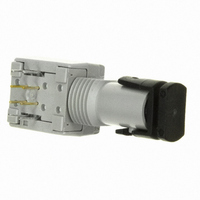
Manufacturer Part Number
HFBR-1414TZ
Description
XMITTER FIBER OPTIC HIGH PWR ST
Manufacturer
Avago Technologies US Inc.
Specifications of HFBR-1414TZ
Wavelength
820nm
Voltage - Forward (vf) Typ
1.7V
Current - Dc Forward (if)
100mA
Voltage - Dc Reverse (vr) (max)
1.8V
Capacitance
55pF
Connector Type
ST
Function
High performance fiber optic communication links for information systems and industrial applications.
Product
Transmitter
Data Rate
160 MBd
Diode Capacitance
55 pF
Maximum Rise Time
6.5 ns
Maximum Fall Time
6.5 ns
Pulse Width Distortion
7.56 ns
Operating Supply Voltage
7 VDC
Maximum Operating Temperature
+ 85 C
Minimum Operating Temperature
- 40 C
Lead Free Status / RoHS Status
Lead free / RoHS Compliant
Spectral Bandwidth
-
Lead Free Status / Rohs Status
Lead free / RoHS Compliant
For Use With
Multimode Glass, Hard Clad Silica
Lead Free Status / RoHS Status
Lead free / RoHS Compliant, Lead free / RoHS Compliant
Other names
516-2039
Available stocks
Company
Part Number
Manufacturer
Quantity
Price
Company:

Part Number:
HFBR-1414TZ
Manufacturer:
TI
Quantity:
5 560
Company:
Part Number:
HFBR-1414TZ
Manufacturer:
Avago Technologies US Inc.
Quantity:
1 871
Part Number:
HFBR-1414TZ
Manufacturer:
AVAGO/安华高
Quantity:
20 000


5 MBd Logic Link Design
If resistor R1 in Figure 2 is 70.4 Ω, a forward current I
of 48 mA is applied to the HFBR-14x4Z LED transmitter.
With I
guaranteed to work with 62.5/125 µm fiber optic cable
over the entire range of 0 to 1750 meters at a data
rate of dc to 5 MBd, with arbitrary data format and
pulse width distortion typically less than 25%. By
setting R
I
achieve lower pulse distortion.
The following example will illustrate the technique for
selecting the appropriate value of I
+5 V
NOTE:
IT IS ESSENTIAL THAT A BYPASS CAPACITOR (0.01 µF TO 0.1 µF
CERAMIC) BE CONNECTED FROM PIN 2 TO PIN 7 OF THE RECEIVER.
TOTAL LEAD LENGTH BETWEEN BOTH ENDS OF THE CAPACITOR
AND THE PINS SHOULD NOT EXCEED 20 MM.
Figure 2. Typical Circuit Configuration.
11
F
DATA IN
= 30 mA, if it is desired to economize on power or
1 K
SELECT R
F
= 48 mA the HFBR-14x4Z/24x2Z logic link is
½ 75451
1
R
R
R
1
1
= 115 Ω, the transmitter can be driven with
1
1
TO SET I
233
V
CC
I
I
F
F
F
V
2
6
7
3
F
TRANSMITTER
HFBR-14xxZ
5V
T
1.5V
15
mA
F
and R
1
.
TRANSMISSION
F
DISTANCE =
Maximum distance required = 400 meters. From Figure
3 the drive current should be 15 mA. From the
transmitter data V
shown in Figure 9.
The curves in Figures 3, 4, and 5 are constructed
assuming no inline splice or any additional system loss.
Should the link consists of any in-line splices, these
curves can still be used to calculate link limits provided
they are shifted by the additional system loss expressed
in dB. For example, Figure 3 indicates that with 48 mA
of transmitter drive current, a 1.75 km link distance is
achievable with 62.5/125 µm fiber which has a
maximum attenuation of 4 dB/km. With 2 dB of
additional system loss, a 1.25 km link distance is still
achievable.
F
= 1.5 V (max.) at I
HFBR-24x2Z
RECEIVER
R
7 & 3
2
6
F
= 15 mA as
TTL DATA OUT
R
L
0.1 µF
V
CC
Related parts for HFBR-1414TZ
Image
Part Number
Description
Manufacturer
Datasheet
Request
R

Part Number:
Description:
FIBER OPTIC CBL SIMPLEX 1=100M
Manufacturer:
Avago Technologies US Inc.
Datasheet:

Part Number:
Description:
FIBER OPTIC CBL SIMPLEX 1=500M
Manufacturer:
Avago Technologies US Inc.
Datasheet:

Part Number:
Description:
FIBER OPTIC CONN LATCH GRY SIMPL
Manufacturer:
Avago Technologies US Inc.
Datasheet:

Part Number:
Description:
FIBER OPTIC CONN LATCH BLU SIMPL
Manufacturer:
Avago Technologies US Inc.
Datasheet:

Part Number:
Description:
XMITTER VERSATILE LINK HORZ
Manufacturer:
Avago Technologies US Inc.
Datasheet:

Part Number:
Description:
Fiber Optic Transmitters, Receivers, Transceivers 1300nm 155MBd 16-pin DIP ST Rx
Manufacturer:
Avago Technologies US Inc.

Part Number:
Description:
FIBER OPTIC CBL DUPLEX 1=100M
Manufacturer:
Avago Technologies US Inc.
Datasheet:
Part Number:
Description:
FIBER OPTIC CBL SIMPLEX 1=500M
Manufacturer:
Avago Technologies US Inc.
Datasheet:
Part Number:
Description:
FIBER OPTIC CBL DUPLEX 1=500M
Manufacturer:
Avago Technologies US Inc.
Datasheet:

Part Number:
Description:
FIBER OPTIC CBL SIMPLEX 1=100M
Manufacturer:
Avago Technologies US Inc.
Datasheet:

Part Number:
Description:
OPTOCOUPLER GATE DRV 2A 16-SOIC
Manufacturer:
Avago Technologies US Inc.
Datasheet:
Part Number:
Description:
OPTOCOUPLER 2CH 2.5A 16-SOIC
Manufacturer:
Avago Technologies US Inc.
Datasheet:

Part Number:
Description:
OPTOCOUPLER GATE DRV 0.4A 16SOIC
Manufacturer:
Avago Technologies US Inc.
Datasheet:

Part Number:
Description:
OPTOCOUPLER 2.0A 250KHZ 8-DIP
Manufacturer:
Avago Technologies US Inc.
Datasheet:

Part Number:
Description:
OPTOCOUPLER 2.0A 250KHZ GW 8-SMD
Manufacturer:
Avago Technologies US Inc.
Datasheet: