HFBR-1414TZ Avago Technologies US Inc., HFBR-1414TZ Datasheet - Page 21
HFBR-1414TZ
Manufacturer Part Number
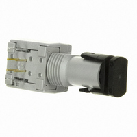
HFBR-1414TZ
Description
XMITTER FIBER OPTIC HIGH PWR ST
Manufacturer
Avago Technologies US Inc.
Specifications of HFBR-1414TZ
Wavelength
820nm
Voltage - Forward (vf) Typ
1.7V
Current - Dc Forward (if)
100mA
Voltage - Dc Reverse (vr) (max)
1.8V
Capacitance
55pF
Connector Type
ST
Function
High performance fiber optic communication links for information systems and industrial applications.
Product
Transmitter
Data Rate
160 MBd
Diode Capacitance
55 pF
Maximum Rise Time
6.5 ns
Maximum Fall Time
6.5 ns
Pulse Width Distortion
7.56 ns
Operating Supply Voltage
7 VDC
Maximum Operating Temperature
+ 85 C
Minimum Operating Temperature
- 40 C
Lead Free Status / RoHS Status
Lead free / RoHS Compliant
Spectral Bandwidth
-
Lead Free Status / Rohs Status
Lead free / RoHS Compliant
For Use With
Multimode Glass, Hard Clad Silica
Lead Free Status / RoHS Status
Lead free / RoHS Compliant, Lead free / RoHS Compliant
Other names
516-2039
Available stocks
Company
Part Number
Manufacturer
Quantity
Price
Company:

Part Number:
HFBR-1414TZ
Manufacturer:
TI
Quantity:
5 560
Company:
Part Number:
HFBR-1414TZ
Manufacturer:
Avago Technologies US Inc.
Quantity:
1 871
Part Number:
HFBR-1414TZ
Manufacturer:
AVAGO/安华高
Quantity:
20 000


Electrical/Optical Characteristics -40 °C to + 85 °C unless otherwise specified
Fiber sizes with core diameter ≤ 100 µm and NA ≤ 0.35, 4.75 V ≤ V
Dynamic Characteristics
-40 °C to +85 °C unless otherwise specified; 4.75 V ≤ V
Notes:
1. 2.0 mm from where leads enter case.
2. 8 mA load (5 x 1.6 mA), RL = 560 Ω.
3. Typical data at T
4. D is the effective diameter of the detector image on the plane of the fiber face. The numerical value is the product of the actual detector diameter
5. Measured at the end of 100/140 µm fiber optic cable with large area detector.
6. Propagation delay through the system is the result of several sequentially-occurring phenomena. Consequently it is a combination of data-rate-
7. As the cable length is increased, the propagation delays increase at 5 ns per meter of length. Data rate, as limited by pulse width distortion, is not
21
Parameter
High Level Output Current
Low Level Output Voltage
High Level Supply Current
Low Level Supply Current
Equivalent NA
Optical Port Diameter
Parameter
Peak Optical Input Power Logic Level HIGH
Peak Optical Input Power Logic Level LOW
Propagation Delay LOW to HIGH
Propagation Delay HIGH to LOW
CAUTION: The small junction sizes inherent to the design of these components increase the components’ susceptibility to damage
from electrostatic discharge (ESD). It is advised that normal static precautions be taken in handling and assembly of these
components to prevent damage and/or degradation which may be induced by ESD.
and the lens magnification.
limiting effects and of transmission-time effects. Because of this, the data-rate limit of the system must be described in terms of time differentials
between delays imposed on falling and rising edges.
affected by increasing cable length if the optical power level at the receiver is maintained.
A
= +25 °C, V
CC
= 5.0 Vdc.
Symbol
I
I
I
NA
D
V
Symbol
P
P
t
t
OH
CCH
CCL
PLHR
PHLR
RH
RL
OL
Min
Min
-25.4
2.9
-24.0
4.0
CC
≤ 5.25 V; BER ≤ 10-9
5
0.4
3.5
6.2
0.50
400
Typ
65
Typ
49
CC
3
3
≤ 5.25 V
Max
250
0.5
6.3
10
Max
-40
0.1
-9.2
120
-10.0
100
Units
µA
V
mA
mA
µm
Units
dBm pk
µW pk
dBm pk
µW pk
dBm pk
µW pk
ns
ns
Conditions
V
P
I
P
V
P
V
P
Conditions
I
I
P
Data Rate =
5 MBd
O
T
T
l
OL
OL
R
R
R
R
O
CC
CC
R
A
A
P
= 8 mA
< -40 dBm
> -24 dBm
< -40 dBm
> -24 dBm
= 18
= 8mA
= 8mA
= -21 dBm,
= +25 °C,
= +25 °C,
= 820 nm
= 5.25 V
= 5.25 V
Reference
Note 4
Reference
Note 5
Note 5
Note 6
Related parts for HFBR-1414TZ
Image
Part Number
Description
Manufacturer
Datasheet
Request
R

Part Number:
Description:
FIBER OPTIC CBL SIMPLEX 1=100M
Manufacturer:
Avago Technologies US Inc.
Datasheet:

Part Number:
Description:
FIBER OPTIC CBL SIMPLEX 1=500M
Manufacturer:
Avago Technologies US Inc.
Datasheet:

Part Number:
Description:
FIBER OPTIC CONN LATCH GRY SIMPL
Manufacturer:
Avago Technologies US Inc.
Datasheet:

Part Number:
Description:
FIBER OPTIC CONN LATCH BLU SIMPL
Manufacturer:
Avago Technologies US Inc.
Datasheet:

Part Number:
Description:
XMITTER VERSATILE LINK HORZ
Manufacturer:
Avago Technologies US Inc.
Datasheet:

Part Number:
Description:
Fiber Optic Transmitters, Receivers, Transceivers 1300nm 155MBd 16-pin DIP ST Rx
Manufacturer:
Avago Technologies US Inc.

Part Number:
Description:
FIBER OPTIC CBL DUPLEX 1=100M
Manufacturer:
Avago Technologies US Inc.
Datasheet:
Part Number:
Description:
FIBER OPTIC CBL SIMPLEX 1=500M
Manufacturer:
Avago Technologies US Inc.
Datasheet:
Part Number:
Description:
FIBER OPTIC CBL DUPLEX 1=500M
Manufacturer:
Avago Technologies US Inc.
Datasheet:

Part Number:
Description:
FIBER OPTIC CBL SIMPLEX 1=100M
Manufacturer:
Avago Technologies US Inc.
Datasheet:

Part Number:
Description:
OPTOCOUPLER GATE DRV 2A 16-SOIC
Manufacturer:
Avago Technologies US Inc.
Datasheet:
Part Number:
Description:
OPTOCOUPLER 2CH 2.5A 16-SOIC
Manufacturer:
Avago Technologies US Inc.
Datasheet:

Part Number:
Description:
OPTOCOUPLER GATE DRV 0.4A 16SOIC
Manufacturer:
Avago Technologies US Inc.
Datasheet:

Part Number:
Description:
OPTOCOUPLER 2.0A 250KHZ 8-DIP
Manufacturer:
Avago Technologies US Inc.
Datasheet:

Part Number:
Description:
OPTOCOUPLER 2.0A 250KHZ GW 8-SMD
Manufacturer:
Avago Technologies US Inc.
Datasheet: