SOIC8EV Microchip Technology, SOIC8EV Datasheet - Page 17
SOIC8EV
Manufacturer Part Number
SOIC8EV
Description
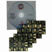
BOARD DEMO 8SOIC/MSOP/TSSOP/DIP
Manufacturer
Microchip Technology
Specifications of SOIC8EV
Mfg Application Notes
Interface Product Design Guide
Main Purpose
Bare Evaluation Board
Embedded
No
Primary Attributes
8- Pin SOIC/DIP/TSSOP/MSOP Evaluation Board
Secondary Attributes
For PICmicro® MCUs, ADCs, DACs and other Devices
Lead Free Status / RoHS Status
Lead free / RoHS Compliant
Utilized Ic / Part
-
Lead Free Status / Rohs Status
Lead free / RoHS Compliant
Available stocks
Company
Part Number
Manufacturer
Quantity
Price
Company:

Part Number:
SOIC8EV
Manufacturer:
Microchip Technology
Quantity:
135


© 2005 Microchip Technology Inc.
2.4.3
The footprints for these components are present to allow maximum flexibility in the use
of this PCB to evaluate a wide range of SOT-23-3 devices. The purpose of these
components may vary depending on the device under evaluation and how it is to be
used in the desired circuit. Refer to the device data sheet for the recommended
components that should be used when evaluating that device.
• Component R1X allows an in-line resistor that can be installed between the
• Component R2X allows a pull-up resistor to be installed for the device pin
• Component R3X allows a pull-down resistor to be installed for the device pin
• Component C1X allows a capacitive load/filter to be installed for the device pin
• Component C1 allows a power supply filtering capacitor to be installed
• Components C2 and C3 allows a device filtering capacitor to be installed
• Components P1, P2, P3, and P4 are not connected and give a footprint (805
2.4.4
Resistor R1X is shorted by default. Therefore, if resistor R1X is to be installed, the trace
across the component must be cut before it is installed (see Figure 2-4).
While evaluating a device, it may be desireable to see the signals on both sides of this
resistor. A test point is available so that both signals may be monitored. This test point
is the avenue between components R3X and C1X (see Figure 2-4).
FIGURE 2-4:
device pin and the PCB pad. This may be required when interfacing this PCB to
other circuits
surface-mount) for a passive component (resistor, capacitor, etc.) to be installed
and jumpered into the PCB circuit. This allows for the evaluation of some simple
device circuits to be implemented on this PCB
Passive Components (R1X, R2X, R3X, C1X, R1, R2, C1, C2, C3,
P1, P2, P3 and P4)
Installing Resistor R1X
Test point when resistor R1X is installed.
Installation and Operation
Test point
This trace must be cut
before resistor R1X can be installed
DS51544A-page 13
Related parts for SOIC8EV
Image
Part Number
Description
Manufacturer
Datasheet
Request
R

Part Number:
Description:
SOIC-8
Manufacturer:
Microchip Technology Inc.
Datasheet:
Part Number:
Description:
SOIC-8
Manufacturer:
Microchip Technology Inc.
Datasheet:
Part Number:
Description:
SOIC
Manufacturer:
Microchip Technology Inc.
Datasheet:
Part Number:
Description:
SOIC-8-TR/256K, 32K X 8, 2.5V SER EE, IND
Manufacturer:
Microchip Technology Inc.
Part Number:
Description:
SOIC 8/150STAND ALONE LIN TRANSCEIVER
Manufacturer:
Microchip Technology Inc.
Datasheet:
Part Number:
Description:
SOIC 20/USB TO SPI PROTOCOL CONVERTER
Manufacturer:
Microchip Technology Inc.
Datasheet:
Part Number:
Description:
SOIC 8/I�/1.5KB OTP, 41 RAM, 6 I/O
Manufacturer:
Microchip Technology Inc.
Part Number:
Description:
soic 8/I�/8-Pin, Flash-Based 8-Bit CMOS Microcontrollers
Manufacturer:
Microchip Technology Inc.
Part Number:
Description:
SOIC/I�/Microcontroller Series EPROM/ROM-Based 8-bit CMOS
Manufacturer:
Microchip Technology Inc.
Part Number:
Description:
SOIC 8/C�/8 Mbit SPI Serial Flash 50MHZ
Manufacturer:
Microchip Technology Inc.
Datasheet:
Part Number:
Description:
Manufacturer:
Microchip Technology Inc.
Datasheet:
Part Number:
Description:
Manufacturer:
Microchip Technology Inc.
Datasheet:
Part Number:
Description:
Manufacturer:
Microchip Technology Inc.
Datasheet: