MCP42XXDM-PTPLS Microchip Technology, MCP42XXDM-PTPLS Datasheet
MCP42XXDM-PTPLS
Specifications of MCP42XXDM-PTPLS


Related parts for MCP42XXDM-PTPLS

MCP42XXDM-PTPLS Summary of contents
Page 1
... Microchip Technology Inc. MCP42XX PICtail™ Plus Daughter Board User’s Guide DS51759A ...
Page 2
... PowerMate, PowerTool, REAL ICE, rfLAB, Select Mode, Total Endurance, UNI/O, WiperLock and ZENA are trademarks of Microchip Technology Incorporated in the U.S.A. and other countries. SQTP is a service mark of Microchip Technology Incorporated in the U.S.A. All other trademarks mentioned herein are property of their respective companies. ...
Page 3
... A.8 Board – Bottom Layer .................................................................................. 35 Appendix B. Bill Of Materials (BOM) Appendix C. Board Testing C.1 Introduction .................................................................................................. 39 C.2 What is Tested ............................................................................................. 40 C.3 What is NOT Tested .................................................................................... 40 Worldwide Sales and Service .................................................................................... 42 © 2008 Microchip Technology Inc. MCP42XX PICTAIL™ PLUS DAUGHTER BOARD USER’S GUIDE Table of Contents DS51759A-page iii ...
Page 4
... MCP42XX PICtail™ Plus Daughter Board User’s Guide NOTES: DS51759A-page iv © 2008 Microchip Technology Inc. ...
Page 5
... Appendix C. “Board Testing” – Describes the testing method for the MCP42XX PICtail Plus Daughter Board User’s Guide and what aspects of the board are and are not tested. © 2008 Microchip Technology Inc. MCP42XX PICTAIL™ PLUS DAUGHTER BOARD USER’S GUIDE ...
Page 6
... Optional arguments mcc18 [options] file [options] Choice of mutually exclusive errorlevel {0|1} arguments selection Replaces repeated text var_name [, var_name...] Represents code supplied by void main (void) user { ... } © 2008 Microchip Technology Inc. Examples ® IDE User’s Guide ...
Page 7
... Local sales offices are also available to help customers. A listing of sales offices and locations is included in the back of this document. Technical support is available through the web site at: http://support.microchip.com DOCUMENT REVISION HISTORY Revision A (September 2008) • Initial Release of this Document. © 2008 Microchip Technology Inc. Preface DS51759A-page 3 ...
Page 8
... MCP42XX PICtail™ Plus Daughter Board User’s Guide NOTES: DS51759A-page 4 © 2008 Microchip Technology Inc. ...
Page 9
... GUI is available, but not supported (as is). This chapter covers the following topics: • What is the MCP42XX PICtail Plus Daughter Board? • What the MCP42XX PICtail Plus Daughter Board Kit includes © 2008 Microchip Technology Inc. MCP42XX PICTAIL™ PLUS DAUGHTER BOARD USER’S GUIDE DS51759A-page 5 ...
Page 10
... IHH Selects source of Terminal A0 Voltage. Either AVDD or VA0 Selects source of Terminal B0 Voltage. Either AVSS or VB0 Selects source of Terminal A1 Voltage. Either AVDD or VA1 Selects source of Terminal B1 Voltage. Either AVSS or VB1 Connects Explorer 16 +5V signal to AVDD signal © 2008 Microchip Technology Inc. ...
Page 11
... Analog and Interface Products Demonstration Boards CD-ROM (DS21912) - MCP42XX PICtail™ Plus Daughter Board User’s Guide, (DS51759) - PICkit Serial Analyzer PC GUI (executable and source code) - supplied “As Is” © 2008 Microchip Technology Inc. Product Overview , 3.3V, 5.0V, or 9.0V) - High Voltage command support SS ...
Page 12
... MCP42XX PICtail™ Plus Daughter Board User’s Guide NOTES: DS51759A-page 8 © 2008 Microchip Technology Inc. ...
Page 13
... Supplied with a “C” program that demonstrates normal and high voltage commands • Demonstrates a split rail application, with digital logic at 3.3V and analog operation at 5.0V © 2008 Microchip Technology Inc. MCP42XX PICTAIL™ PLUS DAUGHTER BOARD USER’S GUIDE , 3.3V, 5.0V, or ...
Page 14
... AV DD JP3 V W1 JP4 V SS VB1 MAX4582L +9. CS0 DD RD14 A Y0 +5.0V RD15 B +3. +9.0V C Name PICkit Serial 6-Pin Interface 2 Pin # SPI Name I C Name 6 SDO — 5 SCK SCL 4 SDI SDA 3 VSS VSS 2 VDD VDD 1 CS — © 2008 Microchip Technology Inc. ...
Page 15
... W pins. Lastly there is a jumper to ensure that drive conflicts do not occur if an external power supply is being used for the AVDD voltage. The default jumper configuration for the shipped demo board is shown in Figure 2-3. © 2008 Microchip Technology Inc. Installation and Operation 2 ...
Page 16
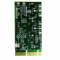
... JP3 - PIC24 AN1 pin AN1 connected to W1 AN1 not connected JP2 - PIC24 AN0 pin AN0 connected to W0 AN0 not connected FIGURE 2-2: MCP42XXDM-PTPLS Jumper Configuration and Oscilloscope Test Points. DS51759A-page 12 JMP2:JMP4 - Terminal B Source JP1 - Explorer 16 5V signal Explorer 16 5V signal connected to ...
Page 17
... FIGURE 2-3: MCP42XX PICtail Plus Daughter Board Layout with Default Jumper Settings Note: This is the Jumper configuration that the board should be shipped with. © 2008 Microchip Technology Inc. Installation and Operation DS51759A-page 13 ...
Page 18
... Section 2.4.1 “Demos with the Explorer 16 Starter Kit”. While the demo using the PICkit Serial Analyzer is discussed in Section 2.4.2 “Demo with the PICkit Serial Analyzer”. Note: Both demos require that the MCP42XXDM-PTPLS board jumper settings are as shown in Figure 2-4. 2.4.1 Demos with the Explorer 16 Starter Kit ...
Page 19
... THE MCP42XXDM-PTPS JUMPER CONFIGURATION Before inserting the board into the Explorer 16 Developers Board, the jumper configuration must be verified. Figure 2-4 shows the configurations of the jumpers. Channel 1 Channel 4 (Program 2 SDO Signal) Channel 3 Channel 2 FIGURE 2-4: MCP4XXDM-PTPLS Jumper Configuration and Oscilloscope Test Points. ...
Page 20
... PICtail Plus header that the MCP42XX PICtail Plus Daughter Board is inserted into. The boards Reset switch and other switches are pointed out. Ensure that the MCP42XXDM-PTPLS is installed in the correct orientation into the Explorer 16 Developers Board. Figure 2-5 shows the location where the daughter board is inserted into the Explorer 16 Developers Board ...
Page 21
... Wiper 1 Saw Wave (Switch S3 not depressed). 2. Increment / Decrement with High Voltage Write to Non-Volatile Wiper 1 Register (Switch S3 depressed). Table 2-2 shows the sequence of steps to demo the MCP42XXDM-PTPLS board with the Explorer 16 Developer’s Board. Figure 2-6 shows the expected output waveform for Program #1 (Wiper 1 Saw Wave) as well as the voltage levels and ranges of the four signals ...
Page 22
... Release the Explorer 16 Developer Board’s S3 push button 20 Unplug Power from the Explorer 16 Developer Board and remove the MCP42XXDM-PTPLS board Note 1: The SDI and SCK signals go from V operating at 3.3V. The VW1 signals go from V DS51759A-page 18 DEMO STEPS USING THE PICDEM HPC EXPLORER DEMO ...
Page 23
... FIGURE 2-6: FIGURE 2-7: © 2008 Microchip Technology Inc. Installation and Operation Screen Capture of Program 1 Output Waveforms. Screen Capture of Program 2 Non-Volatile Write Waveform. DS51759A-page 19 ...
Page 24
... Table 2-3 shows the required hardware to operate the demo. TABLE 2-3: Item # Description 1 PC with USB port running Windows XP 2 PICkit Serial Analyzer Adapter (DV164122) 3 MCP42XXDM-PTPLS 4 Oscilloscope Note 1: A Digital Multi-Meter (DMM) may be used to measure the W pins voltage. DS51759A-page 20 ® Development tool platform, please refer to the ...
Page 25
... Baud” button results in an actual Baud Rate of 9.62 kHz, as shown in Figure 2-10. This reflects the actual Baud Rate based on the PICkit Serial Analyzer’s clock fre- quency. FIGURE 2-9: © 2008 Microchip Technology Inc. Installation and Operation 1st Screen of GUI. Configuring the Baud Rate - Desired Baud Rate. ...
Page 26
... Figure 2-11. To have access to more control of the MCP42XX memory, click on the Advanced tab, and the GUI will display Figure 2-12. FIGURE 2-11: DS51759A-page 22 Configuring the Baud Rate - Actual Baud Rate. Enabling The MCP42XX Chip Select. © 2008 Microchip Technology Inc. ...
Page 27
... Mid-scale value due to board production testing. To write to a desired register, in the desired data entry box and click on the Write button. Figure 2-14 shows an example of writing to the Volatile Wiper 0 register. FIGURE 2-13: © 2008 Microchip Technology Inc. Installation and Operation Advance Screen. Advance Screen - Read Register. ...
Page 28
... MCP42XX PICtail™ Plus Daughter Board User’s Guide FIGURE 2-14: DS51759A-page 24 Advance Screen - Write Register. © 2008 Microchip Technology Inc. ...
Page 29
... Figure 2-15 shows the connections for the Demo using the PICkit Serial Analyzer. Insert PICkit Serial Analyzer into this Header FIGURE 2-15: PICkit Serial Analyzer Demo Jumper Configuration and Oscilloscope Test Points. © 2008 Microchip Technology Inc. Installation and Operation Channel 1 DS51759A-page 25 ...
Page 30
... Turn on oscilloscope and configure as follows: • Channel 1 @ 1V/Division (Note 1) 1b Configure oscilloscope as follows: • Time-base = 100 µs/Division (Note 1) 2 Configure the MCP42XXDM-PTPLS to the jumper settings shown in 3 Insert the PICkit Serial Analyzer into the MCP42XXDM-PTPLS board’s J1 header. Ensure proper orientation of the PICkit Serial Analyzer to the J1 Header ...
Page 31
... Plus Daughter Board and then power up to evaluate if the non-volatile memory value is retained. Note 1: A Digital Multi-Meter (DMM) configured to measure voltage may be used instead of an oscill0scope. © 2008 Microchip Technology Inc. Installation and Operation DEMO STEPS USING THE PICDEM HPC EXPLORER DEMO BOARD (CONTINUED) Action Result ...
Page 32
... MCP42XX PICtail™ Plus Daughter Board User’s Guide NOTES: DS51759A-page 28 © 2008 Microchip Technology Inc. ...
Page 33
... Figure A.3 shows the schematic of the MCP42XX PICtail Plus Daughter Board. Figure A.4 shows the layout for the top layer of the MCP42XX PICtail Plus Daughter Board. The layer order is shown in Figure A-1. FIGURE A-1: © 2008 Microchip Technology Inc. MCP42XX PICTAIL™ PLUS DAUGHTER BOARD USER’S GUIDE LAYER ORDER ...
Page 34
... MCP42XX PICtail™ Plus Daughter Board User’s Guide A.3 BOARD - SCHEMATIC DS51759A-page 30 © 2008 Microchip Technology Inc. ...
Page 35
... A.4 BOARD – TOP SILK-SCREEN LAYER © 2008 Microchip Technology Inc. Schematic and Layouts DS51759A-page 31 ...
Page 36
... MCP42XX PICtail™ Plus Daughter Board User’s Guide A.5 BOARD – TOP COMPONENTS + SILK-SCREEN DS51759A-page 32 © 2008 Microchip Technology Inc. ...
Page 37
... A.6 BOARD – GROUND LAYER © 2008 Microchip Technology Inc. Schematic and Layouts DS51759A-page 33 ...
Page 38
... MCP42XX PICtail™ Plus Daughter Board User’s Guide A.7 BOARD – POWER LAYER DS51759A-page 34 © 2008 Microchip Technology Inc. ...
Page 39
... A.8 BOARD – BOTTOM LAYER © 2008 Microchip Technology Inc. Schematic and Layouts DS51759A-page 35 ...
Page 40
... MCP42XX PICtail™ Plus Daughter Board User’s Guide NOTES: DS51759A-page 36 © 2008 Microchip Technology Inc. ...
Page 41
... DO NOT POPULATE R17 Note 1: The components listed in this Bill of Materials are representative of the PCB assembly. The released BOM used in manufacturing uses all RoHS-compliant components. © 2008 Microchip Technology Inc. MCP42XX PICTAIL™ PLUS DAUGHTER BOARD USER’S GUIDE Description Manufacturer Panasonic ® ...
Page 42
... MCP42XX PICtail™ Plus Daughter Board User’s Guide NOTES: DS51759A-page 38 © 2008 Microchip Technology Inc. ...
Page 43
... Other configurations, Pad connections, and circuit performance are not tested. Channel 1 Channel 4 (Program 2 SDO Signal) Channel 3 Channel 2 FIGURE C-1: Tested Jumper Configuration and Test Points. © 2008 Microchip Technology Inc. MCP42XX PICTAIL™ PLUS DAUGHTER BOARD USER’S GUIDE Channel 4 DS51759A-page 39 ...
Page 44
... Jumpers: JP1, JP2, and JP3 • MAX4582 (U1 (3.3V) switching. • J1: PICkit Serial Analyzer Interface (SPI) • J2: PICkit Serial Analyzer Interface (I • Pads: VA0, VB0, VW0, VA1, VB1, AVDD, and VSS • Test Points: A0, B0, A1, and B1 • Connections to unpopulated components DS51759A-page © 2008 Microchip Technology Inc. ...
Page 45
... NOTES: © 2008 Microchip Technology Inc. Board Testing DS51759A-page 41 ...
Page 46
... Fax: 886-3-572-6459 Taiwan - Kaohsiung Tel: 886-7-536-4818 Fax: 886-7-536-4803 Taiwan - Taipei Tel: 886-2-2500-6610 Fax: 886-2-2508-0102 Thailand - Bangkok Tel: 66-2-694-1351 Fax: 66-2-694-1350 © 2008 Microchip Technology Inc. EUROPE Austria - Wels Tel: 43-7242-2244-39 Fax: 43-7242-2244-393 Denmark - Copenhagen Tel: 45-4450-2828 Fax: 45-4485-2829 France - Paris Tel: 33-1-69-53-63-20 ...