MCP42XXDM-PTPLS Microchip Technology, MCP42XXDM-PTPLS Datasheet - Page 15
MCP42XXDM-PTPLS
Manufacturer Part Number
MCP42XXDM-PTPLS
Description
BOARD DAUGHTER PICTAIL MCP42XX
Manufacturer
Microchip Technology
Type
Other Power Managementr
Datasheet
1.MCP42XXDM-PTPLS.pdf
(46 pages)
Specifications of MCP42XXDM-PTPLS
Main Purpose
Digital Potentiometer
Embedded
Yes, MCU, 8-Bit
Utilized Ic / Part
MCP42XX
Primary Attributes
1 Dual Pot, 10k Ohms, 257 Taps, SPI Interface
Secondary Attributes
2.7 ~ 5.5 V, 150 ppm/°C
Product
Power Management Modules
Silicon Manufacturer
Microchip
Core Architecture
PIC
Core Sub-architecture
PIC24
Silicon Core Number
MCP42XX
Silicon Family Name
PICtail
Kit Contents
Board
For Use With/related Products
MCP42x
Lead Free Status / RoHS Status
Lead free / RoHS Compliant
For Use With
PIC24 Explorer 16 Demo Board
Lead Free Status / RoHS Status
Lead free / RoHS Compliant, Lead free / RoHS Compliant


© 2008 Microchip Technology Inc.
2.3.1
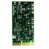
Figure 2-2 shows the component placement of the MCP42XX PICtail Plus Daughter
Board as well as the operation of the board jumpers.
The VAx and VBx pads allow an external voltage source to be applied to the device’s
desired Terminal A or Terminal B pin. The VWx pad is directly connected to the corre-
sponding Terminal W pin, which makes it easy to measure the resulting voltage. The
AVDD pad allows an external power supply to power the board, which should improve
performance compared to powering the board via the PICtail Plus header or the PICkit
Serial Analyzer.
The Printed Circuit Board (PCB) has been designed for the support of the SPI and I
device families (MCP42XX and MCP46XX), so not all components are installed for the
SPI version of the demo board.
2.3.1.1
Figure 2-2 shows the function of the demo board jumpers. Some of the jumpers con-
figure the voltage source of the Terminal A and Terminal B pins while others determine
the connection of the W pins. Lastly there is a jumper to ensure that drive conflicts do
not occur if an external power supply is being used for the AVDD voltage.
The default jumper configuration for the shipped demo board is shown in Figure 2-3.
The Hardware
JUMPER DESCRIPTIONS
Installation and Operation
DS51759A-page 11
2
C
Related parts for MCP42XXDM-PTPLS
Image
Part Number
Description
Manufacturer
Datasheet
Request
R

Part Number:
Description:
Manufacturer:
Microchip Technology Inc.
Datasheet:
Part Number:
Description:
Manufacturer:
Microchip Technology Inc.
Datasheet:
Part Number:
Description:
Manufacturer:
Microchip Technology Inc.
Datasheet:
Part Number:
Description:
Manufacturer:
Microchip Technology Inc.
Datasheet:
Part Number:
Description:
Manufacturer:
Microchip Technology Inc.
Datasheet:
Part Number:
Description:
Manufacturer:
Microchip Technology Inc.
Datasheet:
Part Number:
Description:
Manufacturer:
Microchip Technology Inc.
Datasheet:
Part Number:
Description:
Manufacturer:
Microchip Technology Inc.
Datasheet: