MCP42XXDM-PTPLS Microchip Technology, MCP42XXDM-PTPLS Datasheet - Page 31
MCP42XXDM-PTPLS
Manufacturer Part Number
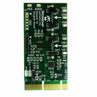
MCP42XXDM-PTPLS
Description
BOARD DAUGHTER PICTAIL MCP42XX
Manufacturer
Microchip Technology
Type
Other Power Managementr
Datasheet
1.MCP42XXDM-PTPLS.pdf
(46 pages)
Specifications of MCP42XXDM-PTPLS
Main Purpose
Digital Potentiometer
Embedded
Yes, MCU, 8-Bit
Utilized Ic / Part
MCP42XX
Primary Attributes
1 Dual Pot, 10k Ohms, 257 Taps, SPI Interface
Secondary Attributes
2.7 ~ 5.5 V, 150 ppm/°C
Product
Power Management Modules
Silicon Manufacturer
Microchip
Core Architecture
PIC
Core Sub-architecture
PIC24
Silicon Core Number
MCP42XX
Silicon Family Name
PICtail
Kit Contents
Board
For Use With/related Products
MCP42x
Lead Free Status / RoHS Status
Lead free / RoHS Compliant
For Use With
PIC24 Explorer 16 Demo Board
Lead Free Status / RoHS Status
Lead free / RoHS Compliant, Lead free / RoHS Compliant


© 2008 Microchip Technology Inc.
TABLE 2-4:
16
17
Note 1:
Step
Now write values to the TCON register (bit 7 to
bit 4) and monitor the effects on the VW1 pin.
Write assorted values to the devices memory
locations and then read the values to see what
is present. If the write is to Non-Volatile mem-
ory, power down (unplug) the MCP42XX PICtail
Plus Daughter Board and then power up to
evaluate if the non-volatile memory value is
retained.
A Digital Multi-Meter (DMM) configured to measure voltage may be used instead of
an oscill0scope.
DEMO STEPS USING THE PICDEM HPC EXPLORER DEMO
BOARD (CONTINUED)
Action
Installation and Operation
The different Potentiometer termi-
nals (A1, W1, and B1), will be either
connected or disconnected depend-
ing on the value.
TCON =
‘x 1110 xxxx’b
‘x 1011 xxxx’b
‘x 1101 xxxx’b
‘x 0111 xxxx’b
‘x 1111 xxxx’b
Result
Result
B1 open,
W1 pulled high
A1 open,
W1 pulled low
W1 floating
A1 open,
W1 connected to
B1 (Zero-Scale)
All terminals con-
nected to their
respective pin
DS51759A-page 27
Related parts for MCP42XXDM-PTPLS
Image
Part Number
Description
Manufacturer
Datasheet
Request
R

Part Number:
Description:
Manufacturer:
Microchip Technology Inc.
Datasheet:
Part Number:
Description:
Manufacturer:
Microchip Technology Inc.
Datasheet:
Part Number:
Description:
Manufacturer:
Microchip Technology Inc.
Datasheet:
Part Number:
Description:
Manufacturer:
Microchip Technology Inc.
Datasheet:
Part Number:
Description:
Manufacturer:
Microchip Technology Inc.
Datasheet:
Part Number:
Description:
Manufacturer:
Microchip Technology Inc.
Datasheet:
Part Number:
Description:
Manufacturer:
Microchip Technology Inc.
Datasheet:
Part Number:
Description:
Manufacturer:
Microchip Technology Inc.
Datasheet: