MCP3909EV-MCU16 Microchip Technology, MCP3909EV-MCU16 Datasheet - Page 23
MCP3909EV-MCU16
Manufacturer Part Number
MCP3909EV-MCU16
Description
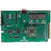
EVALUATION BOARD FOR MCP3909
Manufacturer
Microchip Technology
Datasheets
1.MCP3909T-ISS.pdf
(44 pages)
2.MCP3909T-ISS.pdf
(104 pages)
3.MCP3909EV-MCU16.pdf
(38 pages)
Specifications of MCP3909EV-MCU16
Number Of Adc's
2
Number Of Bits
16
Sampling Rate (per Second)
15k
Data Interface
Serial
Inputs Per Adc
1 Differential
Input Range
±1 V
Voltage Supply Source
Analog and Digital
Operating Temperature
-40°C ~ 85°C
Utilized Ic / Part
MCP3909
Silicon Manufacturer
Microchip
Application Sub Type
ADC
Kit Application Type
Data Converter
Silicon Core Number
MCP3909
Kit Contents
Board
Lead Free Status / RoHS Status
Lead free / RoHS Compliant


TABLE 4-2:
The
integration times and, thus, higher frequencies. The
output frequency value can be calculated with the
following equation:
EQUATION 4-2:
The constant HF
digital settings with the
The detailed timings of the output pulses are described
in the Timing Characteristics table (see Section 1.0
“Electrical Characteristics” and
TABLE 4-3:
© 2009 Microchip Technology Inc.
Where:
F2
F1
V
0
0
0
0
1
1
1
1
0
0
1
1
HF
REF
high-frequency
V
V
HF
G = the PGA gain on Channel 0
C
0
1
OUT
= the RMS differential voltage on
= the RMS differential voltage on
= the frequency constant selected
= the voltage reference
F1
0
0
1
1
0
0
1
1
(
F0
0
1
0
1
Hz
Channel 0
Channel 1
(current channel)
C
ACTIVE POWER OUTPUT FREQUENCY CONSTANT F
)
F0
OUTPUT FREQUENCY CONSTANT HF
0
1
0
1
0
1
0
1
depends on the F
=
ACTIVE POWER HF
FREQUENCY OUTPUT
EQUATION
8.06
--------------------------------------------------------------- -
Table
output
MCLK/2
MCLK/2
MCLK/2
MCLK/2
F
2048 x F
×
128 x F
C
64 x F
32 x F
16 x F
64 x F
32 x F
16 x F
V
4-3.
HF
(Hz)
0
(
V
×
C
HF
REF
21
20
19
18
V
Figure
C
C
C
C
C
C
1
C
C
OUT
×
)
2
OUT0
G
×
1-1).
(MCLK = 3.58 MHz)
HF
has
and F
C
OUT
MCLK/2
MCLK/2
MCLK/2
MCLK/2
MCLK/2
MCLK/2
MCLK/2
MCLK/2
HF
F
lower
OUT1
13.66
C
C
1.71
3.41
6.83
(Hz)
(Hz)
15
15
15
16
16
16
16
7
4.8.1
The MCP3909 also includes, on each output
frequency, a no-load threshold circuit that will eliminate
any creep effects in the meter. The outputs will not
show any pulse if the output frequency falls below the
no-load threshold. This threshold only applies to the
pulse outputs and does not gate any serial data coming
from either the A/D output or the multiplier output. The
minimum output frequency on F
equal to 0.0015% of the maximum output frequency
(respectively F
selections (see
F2, F1, F0 = 011. In this last configuration, the no-load
threshold feature is disabled. The selection of F
determine the start-up current load. In order to respect
the IEC standards requirements, the meter will have to
be designed to allow start-up currents compatible with
the standards by choosing the FC value matching
these
information on no-load threshold, startup current and
other
"IEC Compliant Active Energy Meter Design Using The
MCP3905/6”, (DS00994).
C
(MCLK = 3.58 MHz)
FOR HF
F
OUT
27968.75
HF
with Full-Scale
109.25
109.25
109.25
219.51
219.51
219.51
219.51
meter
requirements.
C
Frequency (Hz)
DC Inputs
(Hz)
MINIMAL OUTPUT FREQUENCY
FOR NO-LOAD THRESHOLD
OUT
0.74
1.48
2.96
5.93
C
Table 4-2
design
and HF
(V
C
REF
FOR FOUT0/1 (V
C
For
HF
= 2.4V)
) for each of the F2, F1 and F0
points,
and
OUT
full scale AC Inputs
MCP3909
F
Table
additional
OUT
Frequency (Hz) with
OUT0/1
with Full-Scale
6070.12
refer
27.21
27.21
27.21
47.42
47.42
47.42
47.42
Frequency (Hz)
AC Inputs
4-3); except when
DS22025B-page 23
0.37
0.74
1.48
2.96
REF
and HF
to
applications
= 2.4V)
AN994,
OUT
C
will
is
Related parts for MCP3909EV-MCU16
Image
Part Number
Description
Manufacturer
Datasheet
Request
R

Part Number:
Description:
Manufacturer:
Microchip Technology Inc.
Datasheet:
Part Number:
Description:
Manufacturer:
Microchip Technology Inc.
Datasheet:
Part Number:
Description:
Manufacturer:
Microchip Technology Inc.
Datasheet:
Part Number:
Description:
Manufacturer:
Microchip Technology Inc.
Datasheet:
Part Number:
Description:
Manufacturer:
Microchip Technology Inc.
Datasheet:
Part Number:
Description:
Manufacturer:
Microchip Technology Inc.
Datasheet:
Part Number:
Description:
Manufacturer:
Microchip Technology Inc.
Datasheet:
Part Number:
Description:
Manufacturer:
Microchip Technology Inc.
Datasheet: