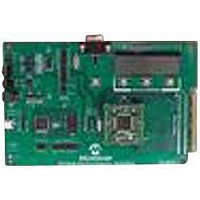
MCP3909EV-MCU16 Microchip Technology, MCP3909EV-MCU16 Datasheet - Page 34

MCP3909EV-MCU16
Manufacturer Part Number
MCP3909EV-MCU16
Description
EVALUATION BOARD FOR MCP3909
Manufacturer
Microchip Technology
Datasheets
1.MCP3909T-ISS.pdf
(44 pages)
2.MCP3909T-ISS.pdf
(104 pages)
3.MCP3909EV-MCU16.pdf
(38 pages)
Specifications of MCP3909EV-MCU16
Number Of Adc's
2
Number Of Bits
16
Sampling Rate (per Second)
15k
Data Interface
Serial
Inputs Per Adc
1 Differential
Input Range
±1 V
Voltage Supply Source
Analog and Digital
Operating Temperature
-40°C ~ 85°C
Utilized Ic / Part
MCP3909
Silicon Manufacturer
Microchip
Application Sub Type
ADC
Kit Application Type
Data Converter
Silicon Core Number
MCP3909
Kit Contents
Board
Lead Free Status / RoHS Status
Lead free / RoHS Compliant
MCP3909
6.2
In most energy meter applications, it will be necessary
to have 2
where N is typically 64, 128 or 256. Controlling the
MCLK of the MCP3909 allows you to control the
sample rate and ultimately the data ready (DR) pulses
for coherent waveform sampling. The following
scheme shows how the TIMER and COMPARATOR
modules of the PIC MCU can be used to generate the
clock for the MCP3909 from either a PLL internal
MCLK. For class 0.2 or class 0.1 meter designs that
require
recommended to shift sample rate with line cycle drift,
e.g. line cycle changes from 60 Hz to 59.1 Hz. This is
shown as option 1 in
FIGURE 6-2:
cycle, 3-phase sampling shown with 6 ADCs
DS22025B-page 34
SDO DR
IRQ
IRQ
50 (or 60 Hz)
Achieving Line Cycle Sampling
with Zero Blind Cycles
N
harmonic
samples for each 50 or 60 Hz line cycle,
Phase A,B,C I & V Data
Option 1
Phase A || B || C
PLL Circuit
x 32768
Figure
analysis
Using the PIC device to control the MCP3909 MCLK to achieve 2
x 6 ADCs
16 bits
6-2.
t
MCP3909
LINE_CYC
using
a
t
SAMPLE
1.96 MHz (60)
1.63 MHz (50)
PLL
128 samples/line cycle
t
SAMPLE
MCP3909
is
3.579 MHz
MCLK input
A simpler lower cost option would be to choose a
frequency that would give an integer number of line
cycles for exactly 50 Hz (or 60 Hz). This is possible
using a 39.3216 MHz crystal for the PIC18F device.
Figure 6-2
achieve 128 samples for each line cycle, 1.63 MHz for
a 50 Hz line, or 1.96 MHz for a 60 Hz line. The
MCP3909 clock can operate from 1 MHz to 4 MHz.
Using this approach, the PIC MCU can gather the
waveform data immediately after the data ready pulse,
at up to 10 MHz. The remainder of the time can be used
to calculate the power measurements to achieve true
line cycle sampling with zero blind cycles.
For more information and firmware, see the Microchip’s
web page for demo board information.
shows example clock frequencies to
MCP3909
PIC MCU
CCP2 / 32768
DR Pulse
X1
© 2009 Microchip Technology Inc.
Option 2
DR
To PIC MCU
N
39.3216 MHz
samples per line
(50 or 60 Hz)
IRQ


