CDB5368 Cirrus Logic Inc, CDB5368 Datasheet - Page 20
CDB5368
Manufacturer Part Number
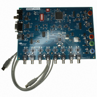
CDB5368
Description
BOARD EVAL FOR CS5368 192KHZ ADC
Manufacturer
Cirrus Logic Inc
Specifications of CDB5368
Number Of Adc's
1
Number Of Bits
24
Sampling Rate (per Second)
192k
Data Interface
Serial
Inputs Per Adc
8 Differential
Input Range
±0.3 V
Voltage Supply Source
Analog and Digital
Operating Temperature
-40°C ~ 85°C
Utilized Ic / Part
CS5368
Description/function
Audio A/D
Operating Supply Voltage
3.3 V
Product
Audio Modules
For Use With/related Products
CS5368
Lead Free Status / RoHS Status
Contains lead / RoHS non-compliant
Lead Free Status / RoHS Status
Lead free / RoHS Compliant, Contains lead / RoHS non-compliant
Other names
598-1157


20
4.3
4.3.1 On-Chip Crystal Oscillator Driver
4.3.2 Externally Generated Master Clock
Master Clock Source
The CS5368 requires a Master Clock that can come from one of two sources: an on-chip crystal oscillator
driver or an externally generated clock.
When using the on-board crystal oscillator driver, the XTI pin (pin 21) is the input for the Master Clock
(MCLK) to the device. The XTO pin (pin 22) must not be used to drive anything other than the oscillator
tank circuitry. When using the on-board crystal driver, the topology shown in
crystal oscillator manufacturer supplies recommended capacitor values. A buffered copy of the XTI input is
available as an output on the MCLK pin (pin 23), which is level-controlled by VLS and may be used to syn-
chronize other parts to the device.
If an external clock is used, the XTI and XTO pins must be grounded, and the MCLK pin becomes an input
for the system master clock. The incoming MCLK should be at the logic level set by the user on the VLS
supply pin.
Figure 7. Crystal Oscillator Topology
XTO
XTI
21
22
Figure 7
must be used. The
CS5368
DS624F4
Related parts for CDB5368
Image
Part Number
Description
Manufacturer
Datasheet
Request
R

Part Number:
Description:
Development Kit
Manufacturer:
Cirrus Logic Inc
Datasheet:
Part Number:
Description:
Development Kit
Manufacturer:
Cirrus Logic Inc
Datasheet:


Part Number:
Description:
High-efficiency PFC + Fluorescent Lamp Driver Reference Design
Manufacturer:
Cirrus Logic Inc
Datasheet:
Part Number:
Description:
Development Kit
Manufacturer:
Cirrus Logic Inc
Datasheet:
Part Number:
Description:
Development Kit
Manufacturer:
Cirrus Logic Inc
Datasheet:

Part Number:
Description:
Development Kit
Manufacturer:
Cirrus Logic Inc
Datasheet:
Part Number:
Description:
Development Kit
Manufacturer:
Cirrus Logic Inc
Datasheet:
Part Number:
Description:
Development Kit
Manufacturer:
Cirrus Logic Inc
Datasheet:
Part Number:
Description:
Development Kit
Manufacturer:
Cirrus Logic Inc
Datasheet:

Part Number:
Description:
EVALUATION BOARD FOR CS8427
Manufacturer:
Cirrus Logic Inc
Datasheet:

Part Number:
Description:
BOARD EVAL FOR CS8416 RCVR
Manufacturer:
Cirrus Logic Inc
Datasheet:

Part Number:
Description:
EVALUATION BOARD FOR CS8420
Manufacturer:
Cirrus Logic Inc
Datasheet:

Part Number:
Description:
KIT DEVELOPMENT EP9315 ARM9
Manufacturer:
Cirrus Logic Inc
Datasheet:

Part Number:
Description:
KIT DEVELOPMENT EP9302 ARM9
Manufacturer:
Cirrus Logic Inc
Datasheet: