CDB5381 Cirrus Logic Inc, CDB5381 Datasheet
CDB5381
Specifications of CDB5381


Related parts for CDB5381


CDB5381 Summary of contents
Page 1
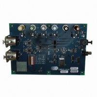
... INPUT Cirrus Logic, Inc. www.cirrus.com Description The CDB5381 evaluation board is an excellent means for quickly evaluating the CS5381 24-bit, stereo A/D con- verter. Evaluation requires a digital signal analyzer, an analog signal source, and a power supply. Also included is a CS8406 digital audio interface trans- ...
Page 2
... Figure 9. Top Layer Silkscreen ..................................................................................................... 12 Figure 10. Top Layer ..................................................................................................................... 13 Figure 11. Bottom Layer................................................................................................................ 14 LIST OF TABLES Table 1. System Connections ........................................................................................................ 4 Table 2. CDB5381 Jumper and Switch Settings ............................................................................ 4 Contacting Cirrus Logic Support For all product questions and inquiries contact a Cirrus Logic Sales Representative. To find one nearest you go to www.cirrus.com IMPORTANT NOTICE “ ...
Page 3
... The evaluation board has been designed to allow interfacing to external systems via the 10-pin header, J13. The schematic for the clock/data input/output is shown in The CDB5381 allows some flexibility as to the generation of the clocks. When the CS5381 and CS8406 are in slave mode, the SCLK and LRCK must be provided via the header, J13. MCLK must be generated from the on board oscillator, Y1 ...
Page 4
... J13 Input/Output for clocks/data S1 Reset for the CDB5381 S2 CDB5381 Configuration Table 2. CDB5381 Jumper and Switch Settings * denotes default factory settings 4 SIGNAL PRESENT -12 V power for the input op-amps +12 V power for the input op-amps +3 power for the CS5381 +2 power for the CS5381 ...
Page 5
... DS563DB1 CDB5381 5 ...
Page 6
... CDB5381 DS563DB1 ...
Page 7
... DS563DB1 CDB5381 7 ...
Page 8
... CDB5381 DS563DB1 ...
Page 9
... DS563DB1 Figure 5. I/O for Clocks/Data Figure 6. CS8406 Digital Audio Interface CDB5381 9 ...
Page 10
... Figure 7. Reset Circuit CDB5381 DS563DB1 ...
Page 11
... DS563DB1 CDB5381 11 ...
Page 12
... CDB5381 DS563DB1 ...
Page 13
... DS563DB1 CDB5381 13 ...
Page 14
... CDB5381 DS563DB1 ...
Page 15
Notes • ...
Page 16
...