STEVAL-ISA050V1 STMicroelectronics, STEVAL-ISA050V1 Datasheet - Page 35
STEVAL-ISA050V1
Manufacturer Part Number
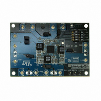
STEVAL-ISA050V1
Description
KIT EVAL PM6641 CHIPSET/DDR2/3
Manufacturer
STMicroelectronics
Type
DC/DC Switching Converters, Regulators & Controllersr
Specifications of STEVAL-ISA050V1
Main Purpose
Special Purpose DC/DC, DDR Memory Supply
Outputs And Type
4, Non-Isolated
Power - Output
14.7W
Voltage - Output
1.05V, 1.5V, 1.8V, 0.9V
Current - Output
4A, 2.8A, 2.5A, 2A
Voltage - Input
2.7 ~ 5.5V
Regulator Topology
Buck
Frequency - Switching
750kHz
Board Type
Fully Populated
Utilized Ic / Part
PM6641
Input Voltage
2.7 V to 5.5 V
Product
Power Management Modules
Silicon Manufacturer
ST Micro
Silicon Core Number
PM6641
Kit Application Type
Power Management - Voltage Regulator
Application Sub Type
Monolithic Voltage Regulator
Kit Contents
Board
Lead Free Status / RoHS Status
Lead free / RoHS Compliant
For Use With/related Products
PM6641
Other names
497-8425
Available stocks
Company
Part Number
Manufacturer
Quantity
Price
Company:

Part Number:
STEVAL-ISA050V1
Manufacturer:
STMicroelectronics
Quantity:
1


PM6641
8
8.1
Components selection
The PM6641 switching regulator sections are buck converters employing a constant
frequency, current mode PWM current loop (see
page 24
The duty-cycle of the buck converter is, in steady-state conditions, given by
Equation 11
The switching frequency directly affects two parameters:
●
●
Inductor selection
Once the switching frequency has been defined, the inductance value depends on the
desired inductor current ripple. Low inductance value means great ripple current that brings
to poor efficiency and great output noise. On the other hand a great current ripple is
desirable for fast transient response when a load step is applied.
Otherwise, great inductance brings to good efficiency but the load transient response is
critical, especially if V
multiplied by the inductor ripple current must be taken in consideration; the PM6641
switching regulators current loop doesn’t need a minimum output ripple in order to work
properly, so a ceramic output capacitor can be considered a good choice.
A good trade-off between the transient response time, the efficiency, the cost and the size is
choosing the inductance value in order to maintain the inductor ripple current between 20%
and 50% (usually 30%) of the maximum output current.
The maximum inductor current ripple, ΔI
With these considerations, the inductance value can be calculated with the following
expression:
Equation 12
where f
ΔI
L
is the inductor current ripple.
Inductor size: greater frequencies mean smaller inductances. In notebook applications,
real estate solutions (i.e. low-profile power inductors) are mandatory also with high
saturation and root mean square (RMS) currents.
Efficiency: switching losses are proportional to the frequency. Generally, higher
frequencies imply lower efficiency.
SW
section for details).
is the switching frequency, V
INmin
- V
OUT
Doc ID 13510 Rev 3
is little. The product of the output capacitor’s ESR
L
=
IN
V
L,MAX
fsw
IN
D =
is the input voltage, V
−
Δ ⋅
V
V
, occurs at the maximum input voltage.
OUT
V
I
OUT
L
IN
Chapter 7.3: SW regulators control loop on
⋅
V
V
OUT
IN
OUT
is the output voltage and
Components selection
35/47
Related parts for STEVAL-ISA050V1
Image
Part Number
Description
Manufacturer
Datasheet
Request
R

Part Number:
Description:
BOARD RGB CTR ST7,STP08C596MTR
Manufacturer:
STMicroelectronics
Datasheet:

Part Number:
Description:
Power Management IC Development Tools Full Speed USB to RS232 Bridge Demo
Manufacturer:
STMicroelectronics
Datasheet:
Part Number:
Description:
Power Management IC Development Tools 2.5W solar eval BRD USB SPV1040 LD39050
Manufacturer:
STMicroelectronics
Datasheet:

Part Number:
Description:
BOARD EVAL FOR MEMS SENSORS
Manufacturer:
STMicroelectronics
Datasheet:

Part Number:
Description:
KIT DEV STARTER ST10F276Z5
Manufacturer:
STMicroelectronics
Datasheet:

Part Number:
Description:
BOARD EVAL HDMI $ VIDEO SWITCH
Manufacturer:
STMicroelectronics
Datasheet:

Part Number:
Description:
BOARD DEMO ACCELEROMETER DIL24
Manufacturer:
STMicroelectronics
Datasheet:

Part Number:
Description:
BOARD STLM75/STDS75/ST72F651
Manufacturer:
STMicroelectronics
Datasheet:

Part Number:
Description:
EVAL BOARD 3AXIS MEMS ACCELLRMTR
Manufacturer:
STMicroelectronics
Datasheet:

Part Number:
Description:
BOARD EVAL 8BIT MICRO + TDE1708
Manufacturer:
STMicroelectronics
Datasheet:
Part Number:
Description:
STMicroelectronics [RIPPLE-CARRY BINARY COUNTER/DIVIDERS]
Manufacturer:
STMicroelectronics
Datasheet:
Part Number:
Description:
STMicroelectronics [LIQUID-CRYSTAL DISPLAY DRIVERS]
Manufacturer:
STMicroelectronics
Datasheet:
Part Number:
Description:
BOARD EVAL FOR MEMS SENSORS
Manufacturer:
STMicroelectronics
Datasheet: