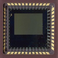
CYIL1SM0300-EVAL Cypress Semiconductor Corp, CYIL1SM0300-EVAL Datasheet - Page 30

CYIL1SM0300-EVAL
Manufacturer Part Number
CYIL1SM0300-EVAL
Description
BOARD EVAL IMAGE SENSOR LUPA-300
Manufacturer
Cypress Semiconductor Corp
Specifications of CYIL1SM0300-EVAL
Sensor Type
CMOS Imaging, Monochrome
Sensing Range
VGA
Interface
SPI
Sensitivity
250 fps
Voltage - Supply
2.5 V ~ 3.3 V
Embedded
No
Utilized Ic / Part
LUPA-300
Lead Free Status / RoHS Status
Contains lead / RoHS non-compliant
Lead Free Status / RoHS Status
Lead free / RoHS Compliant, Contains lead / RoHS non-compliant
Handling Precautions
For proper handling and storage conditions, refer to the Cypress application note AN52561 at www.cypress.com.
Limited Warranty
Cypress Image Sensor Business Unit warrants that the image sensor products to be delivered hereunder if properly used and serviced,
will conform to Seller's published specifications and will be free from defects in material and workmanship for one (1) year following
the date of shipment. If a defect were to manifest itself within 1 (one) year period from the sale date, Cypress will either replace the
product or give credit for the product.
Appendix A: Frequently Asked Questions
Q:
A:
The green lines are the analog signal on the photodiode, which
decrease as a result of exposure. The slope is determined by the
amount of light at each pixel (the more light the steeper the
slope). When the pixels reach the saturation level the analog
signal does not change despite further exposure. As shown,
without any double slope pulse pixels p3 and p4 reaches
saturation before the sample moment of the analog values; no
signal is acquired without double slope. When double slope is
enabled a second reset pulse is given (blue line) at a certain time
before the end of the integration time. This double slope reset
pulse resets the analog signal of the pixels below this level to the
Document Number: 001-00371 Rev. *F
How does the dual (multiple) slope extended dynamic range mode work?
Reset pulse
Total integration time
Double slope reset pulse
Figure 28. Dual Slope Diagram
reset level. After the reset the analog signal starts to decrease
with the same slope as before the double slope reset pulse. If the
double slope reset pulse is placed at the end of the integration
time (90% for instance) the analog signal that reach the
saturation levels are not saturated anymore (this increases the
optical dynamic range) at read out. It is important to note that
pixel signals above the double slope reset level are not influ-
enced by this double slope reset pulse (p1 and p2). If desired,
additional reset pulses can be given at lower levels to achieve
multiple slope.
Read out
p1
p4
p2
p3
Double slope reset time (usually 5-
10% of the total integration time)
Reset level 1
Reset level 2
Saturation level
CYIL1SM0300AA
Page 30 of 31
[+] Feedback


