DC-EM-KT Digi International, DC-EM-KT Datasheet - Page 103
DC-EM-KT
Manufacturer Part Number
DC-EM-KT
Description
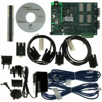
KIT INTEGRATION EM FOR S MODELS
Manufacturer
Digi International
Series
Digi Connect EM®r
Type
MCU Moduler
Specifications of DC-EM-KT
Contents
Module with plug-and-play firmware, Development Board, Documentation, CD, Cables and Power Supply
For Use With/related Products
Digi Connect EM S Module
Lead Free Status / RoHS Status
Contains lead / RoHS non-compliant
Other names
602-1003
DC-EM-01T-KT
DC-EM-02T-KT
DC-EM-01T-KT
DC-EM-02T-KT


Configure Serial Ports
Configure GPIO Pins
Configure Alarms
To configure serial ports, click the Serial Ports link. In contrast to the default web
interface, the Java applet interface does not make use of port profiles to configure serial
port settings. The serial port information displayed is similar to that shown when
configuring serial ports using a Custom Profile in the default web interface. The Serial
Configuration page involves several groups of settings arranged on tabs:
To configure GPIO pins, click the GPIO link. The GPIO pin configuration is very similar
to screen in the default web interface. It shows the current settings for all GPIO pins in the
device, and allows you to change the settings.
As in the default web interface, once you have configured GPIO pins, you can then define
alarms to send notifications in the event of any changes to GPIO pin states.
To configure alarms, click the Alarms link under “Management.”
On the Alarm Configuration screen:
The Basic tab shows basic serial configuration settings, such as baud rate, data
bits, parity, stop bits, and flow control.
The Port Services tab is for configuring TCP and UDP client services.
The Network Services tab is for configuring services that monitor data on the
network and relay it to the serial port.
The Advanced tab shows: Advanced serial configuration settings for TCP and
UDP client services, including whether a socket ID is sent, and whether a
connection should be closed after a certain number of idle seconds or if the
DCD or DSR signals go low.
The checkbox at the top of the screen shows whether alarms are currently
enabled or disabled
The Email Server Information fields show the IP address of the email server
used to send emails when conditions that trigger an alarm occur, and the text to
be included in the “from” field of an alarm-triggered email.
C o n f i g u r i n g t h e D i g i C o n n e c t D e v i c e s
1 0 3
Related parts for DC-EM-KT
Image
Part Number
Description
Manufacturer
Datasheet
Request
R

Part Number:
Description:
KIT DEV EM MOD NO RAVEN DEBUG
Manufacturer:
Digi International
Datasheet:

Part Number:
Description:
KIT JUMP START EM FOR NET+OS 7.X
Manufacturer:
Digi International
Datasheet:
Part Number:
Description:
KIT DEV EM MODULE C MODELS
Manufacturer:
Digi International
Datasheet:
Part Number:
Description:
BOARD DEV EM MODULE JTAG WI-ME
Manufacturer:
Digi International
Datasheet:

Part Number:
Description:
EM 8MB SDRAM 4MB FLASH SINGLE
Manufacturer:
Digi International
Datasheet:

Part Number:
Description:
EM 8MB SDRAM 4MB FLASH SINGLE
Manufacturer:
Digi International
Datasheet:
Part Number:
Description:
EM 8MB SDRAM 4MB FLASH SINGLE
Manufacturer:
Digi International
Part Number:
Description:
EM 8MB SDRAM 4MB FLASH SINGLE
Manufacturer:
Digi International
Datasheet:
Part Number:
Description:
EM 8MB SDRAM 4MB FLASH 25 PAK
Manufacturer:
Digi International
Part Number:
Description:
EM 8MB SDRAM 4MB FLASH 25 PAK
Manufacturer:
Digi International
Part Number:
Description:
EM 8MB SDRAM 4MB FLASH 25 PAK
Manufacturer:
Digi International
Part Number:
Description:
EM 8MB SDRAM 4MB FLASH SINGLE
Manufacturer:
Digi International

Part Number:
Description:
Networking Modules & Development Tools EM Intergration Kit for S Modules
Manufacturer:
Digi International
Datasheet:
Part Number:
Description:
KIT INTEGRATION WI-EM S MODELS
Manufacturer:
Digi International
Datasheet: