DC-EM-KT Digi International, DC-EM-KT Datasheet - Page 92
DC-EM-KT
Manufacturer Part Number
DC-EM-KT
Description
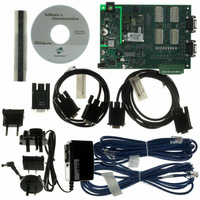
KIT INTEGRATION EM FOR S MODELS
Manufacturer
Digi International
Series
Digi Connect EM®r
Type
MCU Moduler
Specifications of DC-EM-KT
Contents
Module with plug-and-play firmware, Development Board, Documentation, CD, Cables and Power Supply
For Use With/related Products
Digi Connect EM S Module
Lead Free Status / RoHS Status
Contains lead / RoHS non-compliant
Other names
602-1003
DC-EM-01T-KT
DC-EM-02T-KT
DC-EM-01T-KT
DC-EM-02T-KT


9 2
C o n f i g u r a t i o n t h r o u g h t h e D e f a u l t W e b I n t e r f a c e
Set Alarms for GPIO Pin Changes, as Needed
If you want alarms to be issued in the form of email notifications or SNMP traps when a
GPIO pin signals that an event has occurred on the Digi Connect device, go to the Alarms
page and configure those alarms. See "Configure Alarms" on page 93.
Exercise GPIO Pins
Once the GPIO pins and any alarms associated with them have been configured, you
should exercise the GPIO pins to test their configuration.
Exercise GPIO Input
Typically, you will use input signals on GPIO pins to trigger an email alarm, which tells an
administrator or technician that a significant event has occurred within the device. The
process for testing GPIO input is as follows:
1
2
3
4
5
Exercise GPIO Output
The process for testing GPIO output is as follows. In this process, raising a GPIO signal
from the configuration application causes an LED on the development board to turn on.
1
2
3
4
5
On the SW2 bank of switches on the development board, ensure that one of the
GPIO pins is set to high.
On the SW1 bank of switches, set the same GPIO pin to IO.
Configure the GPIO pin for input. See "Configure GPIO Pins" on page 103.
Configure an email alarm for the GPIO pin. See "Configure Alarms" on page 103.
Toggle the SW2 switch several times to generate several email alarms.
On the SW2 bank of switches on the development board, ensure that one of the
GPIO pins is set to High.
On the SW1 bank of switches, set the same GPIO pin to IO.
In the default web interface for the Digi Connect device, click the GPIO link. On
the GPIO page, configure one or more GPIO pins for output. See "Configure GPIO
Pins" on page 103 for details.
Under Administration, click the System Information link. On the System
Information page, click the GPIO link.
Choose Asserted to raise the signal, and then click Set Pins.
An LED on the development board is turned on.
D i g i C o n n e c t F a m i l y U s e r ’ s G u i d e
Related parts for DC-EM-KT
Image
Part Number
Description
Manufacturer
Datasheet
Request
R

Part Number:
Description:
KIT DEV EM MOD NO RAVEN DEBUG
Manufacturer:
Digi International
Datasheet:

Part Number:
Description:
KIT JUMP START EM FOR NET+OS 7.X
Manufacturer:
Digi International
Datasheet:
Part Number:
Description:
KIT DEV EM MODULE C MODELS
Manufacturer:
Digi International
Datasheet:
Part Number:
Description:
BOARD DEV EM MODULE JTAG WI-ME
Manufacturer:
Digi International
Datasheet:

Part Number:
Description:
EM 8MB SDRAM 4MB FLASH SINGLE
Manufacturer:
Digi International
Datasheet:

Part Number:
Description:
EM 8MB SDRAM 4MB FLASH SINGLE
Manufacturer:
Digi International
Datasheet:
Part Number:
Description:
EM 8MB SDRAM 4MB FLASH SINGLE
Manufacturer:
Digi International
Part Number:
Description:
EM 8MB SDRAM 4MB FLASH SINGLE
Manufacturer:
Digi International
Datasheet:
Part Number:
Description:
EM 8MB SDRAM 4MB FLASH 25 PAK
Manufacturer:
Digi International
Part Number:
Description:
EM 8MB SDRAM 4MB FLASH 25 PAK
Manufacturer:
Digi International
Part Number:
Description:
EM 8MB SDRAM 4MB FLASH 25 PAK
Manufacturer:
Digi International
Part Number:
Description:
EM 8MB SDRAM 4MB FLASH SINGLE
Manufacturer:
Digi International

Part Number:
Description:
Networking Modules & Development Tools EM Intergration Kit for S Modules
Manufacturer:
Digi International
Datasheet:
Part Number:
Description:
KIT INTEGRATION WI-EM S MODELS
Manufacturer:
Digi International
Datasheet: