PK-HCS12C32 SofTec Microsystems SRL, PK-HCS12C32 Datasheet - Page 8
PK-HCS12C32
Manufacturer Part Number
PK-HCS12C32
Description
KIT STARTER USB FOR MC9S12C32
Manufacturer
SofTec Microsystems SRL
Datasheet
1.PK-HCS12C32.pdf
(42 pages)
Specifications of PK-HCS12C32
Kit Contents
Emulator/Programmer
Evaluation Board For
Peak Reflow Compatible (260 C)
Leaded Process Compatible
No
Interface Type
Serial
For Use With
MC9S12C32 Microcontroller
Lead Free Status / RoHS Status
Contains lead / RoHS non-compliant
Other names
520-1015


resources. It does not use any user memory or locations in the memory map and does not
share any on-chip peripherals. The background debug module (BDM) uses a single-wire
communication interface to allow non-intrusive access to target system memory and
registers.
PK-HCS12C32 features a USB-to-BDM circuitry which allows the host PC to communicate
to the microcontroller through a standard USB cable.
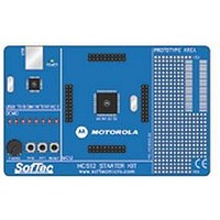
PK-HCS12C32 Board Layout
The PK-HCS12C32 board has the following hardware features:
1. A “USB to BDM Interface” section. It contains the circuitry needed to electrically and
2. A “Demo” section. It features a RESET push-button, two user push-buttons, a
3. A “MCU” section. It contains a soldered, 80-pin MC9S12C32 device (in QFP package)
4. A “Prototype” section. You can wire your own circuit here. The prototype section
logically translate BDM-like commands sent by the host PC through the USB cable to
the BDM interface of the microcontroller. The PK-HCS12C32 board is powered (at 5 V)
by the USB bus.
potentiometer and eight user LEDs.
with connectors to access the I/O pins of the microcontroller for expansion prototyping.
A 16 MHz crystal oscillator (in Colpitts configuration) is provided, and the microcontroller
is configured to work in single-chip mode (MODA = MODB = 0).
features both a standard, thru-hole area (for mounting traditional components) and a
SMD area (for soldering SMD components in SOIC package).
PK-HCS12C32 User's Manual
Page 7
1
Related parts for PK-HCS12C32
Image
Part Number
Description
Manufacturer
Datasheet
Request
R

Part Number:
Description:
BUZZER PIEZO 4.1KHZ 14MM PC MT
Manufacturer:
Mallory Sonalert Products Inc
Datasheet:

Part Number:
Description:
BUZZER PIEZO 3KHZ 24MM PC MT
Manufacturer:
Mallory Sonalert Products Inc
Datasheet:

Part Number:
Description:
BUZZER PIEZO 3.5KHZ 30MM PC MT
Manufacturer:
Mallory Sonalert Products Inc
Datasheet:

Part Number:
Description:
BUZZER PIEZO 2.5KHZ 30MM PC MT
Manufacturer:
Mallory Sonalert Products Inc
Datasheet:

Part Number:
Description:
BUZZER PIEZO 3.8KHZ 23MM PC MT
Manufacturer:
Mallory Sonalert Products Inc
Datasheet:

Part Number:
Description:
BUZZER PIEZO 3KHZ 24MM PC MT
Manufacturer:
Mallory Sonalert Products Inc
Datasheet:

Part Number:
Description:
AUD SIG DEVICE 3-24VDC FLANGE
Manufacturer:
Mallory Sonalert Products Inc
Datasheet:

Part Number:
Description:
AUD SIG DEVICE 3-24VDC PCB
Manufacturer:
Mallory Sonalert Products Inc
Datasheet:

Part Number:
Description:
AUD SIG DEVICE 3-28VDC FLANGE
Manufacturer:
Mallory Sonalert Products Inc
Datasheet:

Part Number:
Description:
AUD SIG DEVICE 3-28VDC FLANGE
Manufacturer:
Mallory Sonalert Products Inc
Datasheet:

Part Number:
Description:
AUD SIG DEVICE 3-28VDC FLANGE
Manufacturer:
Mallory Sonalert Products Inc
Datasheet:

Part Number:
Description:
AUD SIG DEVICE 3-28VDC FLANGE
Manufacturer:
Mallory Sonalert Products Inc
Datasheet:

Part Number:
Description:
BUZZER PIEZO 3.5KHZ 28MM PANEL
Manufacturer:
Mallory Sonalert Products Inc
Datasheet:

Part Number:
Description:
AUD SIG DEVICE 4-8VDC FLANGE
Manufacturer:
Mallory Sonalert Products Inc
Datasheet:

Part Number:
Description:
BUZZER PIEZO 2.5KHZ 23MM PC MT
Manufacturer:
Mallory Sonalert Products Inc
Datasheet: