SUPERPRO 501S Xeltek, SUPERPRO 501S Datasheet - Page 68
SUPERPRO 501S
Manufacturer Part Number
SUPERPRO 501S
Description
PROGRAMMER UNIVERSAL 48-PIN
Manufacturer
Xeltek
Series
SuperPro 501Sr
Type
Universal, Stand Aloner
Datasheet
1.CX1016.pdf
(91 pages)
Specifications of SUPERPRO 501S
Contents
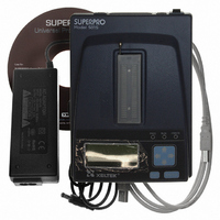
Programmer with 48-Pin DIP Socket, AC Adapter, Software CD, USB Cable, Users Manual
Ic Product Type
Programmer, Universal
Ic Interface Type
USB
No. Of Devices Supported
22488
Kit Contents
SuperPro 501S Programmer, AC Adapter, CD
Rohs Compliant
Yes
For Use With/related Products
E/EPROM, FLASH, PLD, Micros and more listed on Device Sheet, 21,000+ Devices Supported
For Use With
415-1029 - SOCKET ADAPTER FOR SDIP42415-1028 - SOCKET ADAPTER FOR TQFP32415-1027 - SOCKET ADAPTER FOR TSOP56415-1025 - SOCKET ADAPTER FOR SOIC20415-1024 - SOCKET ADAPTER FOR TSOP40415-1023 - SOCKET ADAPTER FOR SOP44415-1022 - SOCKET ADAPTER FOR TSOP56415-1019 - SOCKET ADAPTER FOR SOIC16/SOIC8415-1018 - SOCKET ADAPTER FOR SOIC28415-1015 - SOCKET ADAPTER FOR PLCC28415-1014 - SOCKET ADAPTER FOR PLCC20415-1013 - SOCKET ADAPTER FOR PLCC32415-1017 - SOCKET ADAPTER FOR PLCC44
Lead Free Status / RoHS Status
Lead free by exemption / RoHS compliant by exemption
Other names
415-1046
SP501S
SP501S


Set Options
Select Operation Option from the Option menu to open the Operation Option
screen. Set each of the following options:
Superpro
After confirmation, the system loads data into the buffer.
Make sure the loaded data is correct by viewing on the Buffer Edit
window. Refer to Buffer Menu on page 26 for detailed information.
To read the data from a master chip, complete the following
steps: – Insert the master chip in the socket.
– Select Read on the Device Operation window of the main screen. The
– Make sure the loaded data is correct by viewing on the Buffer Edit window.
– If desired, you can save the data to a disk for later use. Refer to Save on
Insertion Test option to indicate whether to check the pin contact before
programming
Device ID Check option to indicate whether to check the ID of the device
before programming
Beeper option to indicate whether the beeper beeps when the operation
succeeds or fails
Auto Increment Function option to indicate an automatic increase in the label
number written to each chip
Address Change option to indicate a different start and end address for the
programming zone of the device
Verification Mode option to select a specific VCC voltage to ensure that the
chip is programmed correctly
Note: Some Hex or S record files contain non‐zero file start address. In this
Note: The read function is not available for some devices, including those
system copies the data from the master chip into the memory buffer.
Refer to Buffer Menu on page 26 for detailed information.
page 25 for detailed information on saving files.
®
5000 User’s Guide
case, enter the start address in the File Address box.
that have been encrypted.
68
Related parts for SUPERPRO 501S
Image
Part Number
Description
Manufacturer
Datasheet
Request
R

Part Number:
Description:
PROGRAMMER UNIVERSAL 48-PIN
Manufacturer:
Xeltek
Datasheet:

Part Number:
Description:
SUPERPRO 501S N*CLUSTER Gang Programmer
Manufacturer:
Xeltek


Part Number:
Description:
PROGRAMMER UNIV STANDALONE W/USB
Manufacturer:
Xeltek
Datasheet:


Part Number:
Description:
SUPERPRO 3000U IC Device Programmer In X4 CLUSTER
Manufacturer:
Xeltek

Part Number:
Description:
SUPERPRO 3000U N*CLUSTER Gang Programmer
Manufacturer:
Xeltek


Part Number:
Description:
SOCKET ADAPTER FOR SOIC16/SOIC8
Manufacturer:
Xeltek
Datasheet:

Part Number:
Description:
Flash 256MB COMPACT FLASH CARD
Manufacturer:
Xeltek