H5CX-L8-N AC100-240 Omron, H5CX-L8-N AC100-240 Datasheet - Page 38
H5CX-L8-N AC100-240
Manufacturer Part Number
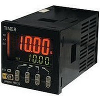
H5CX-L8-N AC100-240
Description
RELAY TIMER DGTL SPDT 100/240VAC
Manufacturer
Omron
Series
H5CXr
Specifications of H5CX-L8-N AC100-240
Relay Type
Integrated
Function
Programmable (Multi-Function)
Circuit
SPDT (1 Form C)
Delay Time
0.001 Sec ~ 9999 Hrs
Output Type
Mechanical Relay
Contact Rating @ Voltage
5A @ 250VAC
Voltage - Supply
100 ~ 240VAC
Mounting Type
Socket
Termination Style
8 Pin Socketable
Timing Adjustment Method
Up/Down Digit Keys
Timing Initiate Method
Input Voltage, Trigger Signal
Time Range
0.001s-9999hr
Power Consumption
6.2VA
Reset Time
20ms
Character Size
11.5mm
Time Range Min
0.001s
Supply Voltage Min
100VAC
Connector Type
8-Pin Socket
Signal Input Type
PNP/NPN
No. Of Digits / Alpha
4
Rohs Compliant
Yes
Lead Free Status / RoHS Status
Lead free / RoHS Compliant
For Use With
PNP/NPN
Lead Free Status / RoHS Status
Lead free / RoHS Compliant, Lead free / RoHS Compliant
Other names
H5CXL8NAC100240
Z2999
Z2999


■ Characteristics
Note 1. The values are based on the set value.
■ Inrush Current (Reference Values)
Accuracy of operating time
and setting error (including
temperature and voltage in-
fluences) (See note 1.)
Insulation resistance
Dielectric strength
Impulse withstand voltage
Noise immunity
Static immunity
Vibration resistance
Shock resistance
Approved safety
standards (See note 2.)
EMC
Degree of protection
Weight
12 to 24 VDC 26.4 VDC
Voltage
2. The Y92S-29 Waterproof Packing and Y92F-30 Flush Mounting Adapter are necessary to ensure IP66, NEMA4, and UL Type 4X water-
proofing between the H5CX and installation panel.
Item
Applied voltage
Power-ON start: ±0.02% ±0.05 s max. Rated against set value
Signal start (minimum pulse width of 20 ms): ±0.01% ±0.03 s max. Rated against set value
Signal start (minimum pulse width of 1 ms): ±0.01% ±3 ms max.
If the set value is within the sensor waiting time at startup the control output of the H5CX will not turn ON until the
sensor waiting time passes.
100 MΩ min. (at 500 VDC) between current-carrying terminal and exposed non-current-carrying metal parts
2,000 VAC, 50/60 Hz for 1 min between current-carrying metal parts and non-current-carrying metal parts
1,000 VAC, 50/60 Hz for 1 min between control output, power supply, and input circuit
1.0 kV (between power terminals)
1.5 kV (between current-carrying terminal and exposed non-current-carrying metal parts)
±480 V (between power terminals) and ±600 V (between input terminals), square-wave noise by noise simulator
(pulse width: 100 ns/1 µs, 1-ns rise)
Destruction: 15 kV
Malfunction: 8 kV
Destruction: 10 to 55 Hz with 0.75-mm single amplitude each in three directions, 2 hours each
Malfunction: 10 to 55 Hz with 0.35-mm single amplitude each in three directions, 10 min each
Destruction: 294 m/s
Malfunction: 196 m/s
UL508/Listing, UL50 Type 4X for indoor use (enclosure rating), CSA C22.2 No. 14, conforms to EN61812-1 (Pollution
degree 2/overvoltage category III)
Conforms to VDE0106/P100 (finger protection).
(EMI)
Emission Enclosure:
(EMS)
Immunity ESD:
Immunity RF-interference:
Immunity Conducted
Disturbance:
Immunity Burst:
Immunity Surge:
Panel surface: IP66 and NEMA4 (indoors), and UL Type 4X (indoors) (See note 2.)
Approx. 140 g
6 A
Inrush current
(peak value)
2
2
each in three directions
each in three directions
1.2 ms
EN61812-1
EN55011 Group 1 class A
EN61812-1
EN61000-4-2:
EN61000-4-3:
EN61000-4-6:
EN61000-4-4:
EN61000-4-5:
Time
H5CX-BWSD
6 kV contact discharge (level 2)
8 kV air discharge (level 3)
10 V/m (Amplitude-modulated, 80 MHz to 1 GHz) (level 3);
10 V/m (Pulse-modulated, 900 MHz ±5 MHz) (level 3)
10 V (0.15 to 80 MHz) (level 3)
2 kV power-line (level 3);
1 kV I/O signal-line (level 4)
1 kV line to lines (power and output lines) (level 3);
2 kV line to ground (power and output lines) (level 3)
H5CX-B
38
Related parts for H5CX-L8-N AC100-240
Image
Part Number
Description
Manufacturer
Datasheet
Request
R

Part Number:
Description:
RELAY TIMER DIGITAL SPDT 100/240
Manufacturer:
Omron
Datasheet:

Part Number:
Description:
G6S-2GLow Signal Relay
Manufacturer:
Omron Corporation
Datasheet:
Part Number:
Description:
Compact, Low-cost, SSR Switching 5 to 20 A
Manufacturer:
Omron Corporation
Datasheet:
Part Number:
Description:
Manufacturer:
Omron Corporation
Datasheet:
Part Number:
Description:
Manufacturer:
Omron Corporation
Datasheet:
Part Number:
Description:
Manufacturer:
Omron Corporation
Datasheet:
Part Number:
Description:
Manufacturer:
Omron Corporation
Datasheet:
Part Number:
Description:
Manufacturer:
Omron Corporation
Datasheet:
Part Number:
Description:
Manufacturer:
Omron Corporation
Datasheet: