TV04A171JB-G Comchip Technology, TV04A171JB-G Datasheet - Page 39
TV04A171JB-G
Manufacturer Part Number
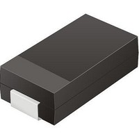
TV04A171JB-G
Description
TVS 400W 170V BIDIRECT SMA
Manufacturer
Comchip Technology
Specifications of TV04A171JB-G
Voltage - Reverse Standoff (typ)
170V
Voltage - Breakdown
189V
Power (watts)
400W
Polarization
Bidirectional
Mounting Type
Surface Mount
Package / Case
DO-214AC, SMA
Channels
1 Channel
Clamping Voltage
275 V
Operating Voltage
3.5 V
Breakdown Voltage
189 V
Peak Surge Current
40 A
Peak Pulse Power Dissipation
400 W
Lead Free Status / RoHS Status
Lead free / RoHS Compliant


12. Absolute Maximum Ratings
13. Operating Ranges
February 23, 2010 S29AL008J_00_09
Notes
1. Minimum DC voltage on input or I/O pins is –0.5 V. During voltage transitions, input or I/O pins may overshoot V
2. Minimum DC input voltage on pins A9, OE#, and RESET# is -0.5 V. During voltage transitions, A9, OE#, and RESET# may overshoot V
3. No more than one output may be shorted to ground at a time. Duration of the short circuit should not be greater than one second.
4. Stresses above those listed under Absolute Maximum Ratings may cause permanent damage to the device. This is a stress rating only;
Note
Operating ranges define those limits between which the functionality of the device is guaranteed.
Parameter
Storage Temperature Plastic Packages
Ambient Temperature with Power Applied
Voltage with Respect to Ground
Output Short Circuit Current
Parameter
Ambient Temperature
V
CC
up to 20 ns. See
pins may overshoot to V
to –2.0 V for periods of up to 20 ns. See
14.0 V for periods up to 20 ns.
functional operation of the device at these or any other conditions above those indicated in the operational sections of this data sheet is
not implied. Exposure of the device to absolute maximum rating conditions for extended periods may affect device reliability.
V
A9, OE#, and RESET#
All other pins
CC
Supply Voltages
(Note 1)
(Note 1)
Figure 13.1 on page
(Note 2)
CC
(Note 3)
+2.0 V for periods up to 20 ns. See
D a t a
+2.0 V
+0.5 V
+0.8 V
–0.5 V
–2.0 V
2.0 V
Figure 13.1 Maximum Negative Overshoot Waveform
Figure 13.2 Maximum Positive Overshoot Waveform
V
V
CC
CC
39. Maximum DC voltage on input or I/O pins is
Figure 13.1 on page
S h e e t
S29AL008J
20 ns
20 ns
39. Maximum DC input voltage on pin A9 is +12.5 V which may overshoot to
Figure 13.2 on page
Extended (N) Devices
Industrial (I) Devices
20 ns
20 ns
Regulated
Full
20 ns
39.
V
CC
+0.5 V. During voltage transitions, input or I/O
–0.5 V to V
–65° C to +150° C
–65° C to +125° C
–0.5 V to +12.5 V
–0.5 V to +4.0 V
200 mA
Rating
CC
–40°C to +125°C
–40° C to +85° C
+0.5 V
3.0 V to 3.6 V
2.7 V to 3.6 V
SS
Range
to –2.0 V for periods of
39
SS
Related parts for TV04A171JB-G
Image
Part Number
Description
Manufacturer
Datasheet
Request
R

Part Number:
Description:
Manufacturer:
Comchip Technology Corporation
Datasheet:
Part Number:
Description:
Manufacturer:
Comchip Technology Corporation
Datasheet:
Part Number:
Description:
Manufacturer:
Comchip Technology Corporation
Datasheet:
Part Number:
Description:
Manufacturer:
Comchip Technology Corporation
Datasheet:
Part Number:
Description:
Manufacturer:
Comchip Technology Corporation
Datasheet:
Part Number:
Description:
Manufacturer:
Comchip Technology Corporation
Datasheet:
Part Number:
Description:
Manufacturer:
Comchip Technology Corporation
Datasheet:
Part Number:
Description:
Manufacturer:
Comchip Technology Corporation
Datasheet:
Part Number:
Description:
Manufacturer:
Comchip Technology Corporation
Datasheet:
Part Number:
Description:
Manufacturer:
Comchip Technology Corporation
Datasheet:
Part Number:
Description:
Manufacturer:
Comchip Technology Corporation
Datasheet:
Part Number:
Description:
Manufacturer:
Comchip Technology Corporation
Datasheet:
Part Number:
Description:
Manufacturer:
Comchip Technology Corporation
Datasheet:
Part Number:
Description:
Manufacturer:
Comchip Technology Corporation
Datasheet:
Part Number:
Description:
Manufacturer:
Comchip Technology Corporation
Datasheet: