TAJE337M004RNJ AVX Corporation, TAJE337M004RNJ Datasheet - Page 11
TAJE337M004RNJ
Manufacturer Part Number
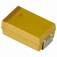
TAJE337M004RNJ
Description
CAPACITOR TANT 330UF 4V 20% SMD
Manufacturer
AVX Corporation
Series
TAJr
Type
Moldedr
Specifications of TAJE337M004RNJ
Capacitance
330µF
Voltage - Rated
4V
Tolerance
±20%
Operating Temperature
-55°C ~ 125°C
Mounting Type
Surface Mount
Package / Case
2917 (7343 Metric)
Size / Dimension
0.287" L x 0.169" W (7.30mm x 4.30mm)
Height
0.161" (4.10mm)
Manufacturer Size Code
E
Features
General Purpose
Lead Free Status / RoHS Status
Lead free / RoHS Compliant
Lead Spacing
-
Esr (equivalent Series Resistance)
-
Lead Free Status / RoHS Status
Compliant, Lead free / RoHS Compliant
Other names
TAJE337M004R
TAJE337M004R
TAJE337M004R


Technical Summary and
Application Guidelines
1.3.2 Tangent of Loss Angle (tan ).
This is a measurement of the energy loss in the capacitor. It
is expressed as tan
divided by its reactive power at a sinusoidal voltage of spec-
ified frequency. Terms also used are power factor, loss factor
and dielectric loss. Cos (90 - ) is the true power factor. The
measurement of tan
bridge which supplies a 0.5Vpk-pk 120Hz sinusoidal signal,
free of harmonics with a maximum bias of 2.2Vdc.
1.3.3 Frequency dependence of Dissipation Factor.
Dissipation Factor increases with frequency as shown in the
typical curves:
1.3.4 Temperature dependence of Dissipation
Dissipation factor varies with temperature as the typical curves
show. For maximum limits please refer to ratings tables.
1.4 IMPEDANCE, (Z) AND EQUIVALENT
1.4.1 Impedance, Z.
This is the ratio of voltage to current at a specified frequency.
Three factors contribute to the impedance of a tantalum capac-
itor; the resistance of the semiconductor layer; the capacitance
value and the inductance of the electrodes and leads.
At high frequencies the inductance of the leads becomes
a limiting factor. The temperature and frequency behavior
of these three factors of impedance determine the behavior
0.1
50
1.8
1.7
1.6
1.5
1.4
1.3
1.2
1.1
0.9
0.8
5
1
0.1
1
-55
SERIES RESISTANCE (ESR)
Factor.
Typical DF vs Temperature
Typical DF vs Frequency
-5
Temperature (Celcius)
1
and is the power loss of the capacitor
Frequency (kHz)
is carried out using a measuring
45
10
95
100
of the impedance Z. The impedance is measured at 20°C
and 100kHz.
1.4.2 Equivalent Series Resistance, ESR.
Resistance losses occur in all practical forms of capacitors.
These are made up from several different mechanisms,
including resistance in components and contacts, viscous
forces within the dielectric and defects producing bypass
current paths. To express the effect of these losses they are
considered as the ESR of the capacitor. The ESR is frequency
dependent and can be found by using the relationship;
Where f is the frequency in Hz, and C is the capacitance in
farads.
The ESR is measured at 20°C and 100kHz.
ESR is one of the contributing factors to impedance, and
at high frequencies (100kHz and above) it becomes the
dominant factor. Thus ESR and impedance become almost
identical, impedance being only marginally higher.
1.4.3 Frequency dependence of Impedance and ESR.
ESR and Impedance both increase with decreasing frequency.
At lower frequencies the values diverge as the extra contri-
butions to impedance (due to the reactance of the capacitor)
become more significant. Beyond 1MHz (and beyond the
resonant point of the capacitor) impedance again increases
due to the inductance of the capacitor.
100
0.1
4.5
3.5
2.5
1.5
0.5
10
1
5
4
3
2
1
0
0.1
0.1
Typical Impedance vs Frequency
Typical ESR vs Frequency
ESR =
1
1
Frequency (kHz)
Frequency (kHz)
tan
2 fC
10
10
100
100
1000
1000
39
Related parts for TAJE337M004RNJ
Image
Part Number
Description
Manufacturer
Datasheet
Request
R

Part Number:
Description:
Manufacturer:
AVX Corporation
Datasheet:
Part Number:
Description:
Manufacturer:
AVX Corporation
Datasheet:
Part Number:
Description:
Manufacturer:
AVX Corporation
Datasheet:
Part Number:
Description:
Manufacturer:
AVX Corporation
Datasheet:
Part Number:
Description:
Manufacturer:
AVX Corporation
Datasheet: