TAJE337M004RNJ AVX Corporation, TAJE337M004RNJ Datasheet - Page 16
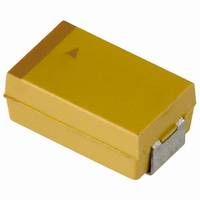
TAJE337M004RNJ
Manufacturer Part Number
TAJE337M004RNJ
Description
CAPACITOR TANT 330UF 4V 20% SMD
Manufacturer
AVX Corporation
Series
TAJr
Type
Moldedr
Specifications of TAJE337M004RNJ
Capacitance
330µF
Voltage - Rated
4V
Tolerance
±20%
Operating Temperature
-55°C ~ 125°C
Mounting Type
Surface Mount
Package / Case
2917 (7343 Metric)
Size / Dimension
0.287" L x 0.169" W (7.30mm x 4.30mm)
Height
0.161" (4.10mm)
Manufacturer Size Code
E
Features
General Purpose
Lead Free Status / RoHS Status
Lead free / RoHS Compliant
Lead Spacing
-
Esr (equivalent Series Resistance)
-
Lead Free Status / RoHS Status
Compliant, Lead free / RoHS Compliant
Other names
TAJE337M004R
TAJE337M004R
TAJE337M004R


Technical Summary and
Application Guidelines
3.1 STEADY-STATE
Tantalum Dielectric has essentially no wear out mechanism
and in certain circumstances is capable of limited self
healing. However, random failures can occur in operation.
The failure rate of Tantalum capacitors will decrease with time
and not increase as with other electrolytic capacitors and
other electronic components.
The useful life reliability of the Tantalum capacitor is affected
by three factors. The equation from which the failure rate can
be calculated is:
where FU is a correction factor due to operating
Base failure rate.
Standard tantalum product conforms to Level M reliability
(i.e., 1%/1000 hrs.) at rated voltage, rated temperature,
and 0.1 /volt circuit impedance. This is known as the
base failure rate, FB, which is used for calculating operating
reliability. The effect of varying the operating conditions on
failure rate is shown on this page.
Operating voltage/voltage derating.
If a capacitor with a higher voltage rating than the maximum
line voltage is used, then the operating reliability will be
improved. This is known as voltage derating.
The graph, Figure 2a, shows the relationship between volt-
age derating (the ratio between applied and rated voltage)
and the failure rate. The graph gives the correction factor FU
for any operating voltage.
44
SECTION 3
RELIABILITY AND CALCULATION OF FAILURE RATE
F = FU x FT x FR x FB
voltage/voltage derating
FT is a correction factor due to operating
temperature
FR is a correction factor due to circuit series
resistance
FB is the basic failure rate level. For standard
Tantalum product this is 1%/1000 hours
Useful life reliability can be altered by voltage
derating, temperature or series resistance
Infant
Mortalities
Figure 1. Tantalum Reliability Curve
Infinite Useful Life
Figure 2b. Gives our recommendation for voltage derating
Figure 2a. Correction factor to failure rate F for voltage
0.0010
1.0000
0.1000
0.0100
0.0001
1.0
0.9
0.8
0.7
0.6
0.5
0.4
0.3
0.2
0.1
Figure 2c. Gives voltage derating recommendations
40
30
20
10
0.01
derating of a typical component (60% con. level).
0
0
0
4 6.3 10
0.1
as a function of circuit impedance.
to be used in typical applications.
0.1
0.2
Applied Voltage / Rated Voltage
Circuit Resistance (Ohm/V)
0.3
1.0
16 20
Rated Voltage (V)
Recommended Range
0.4
0.5
10
25
0.6
Low Impedance Circuit
100
0.7
Specified Range in
35
in General Circuit
Specified Range
0.8
1000
0.9
10000
1
50
Related parts for TAJE337M004RNJ
Image
Part Number
Description
Manufacturer
Datasheet
Request
R

Part Number:
Description:
Manufacturer:
AVX Corporation
Datasheet:
Part Number:
Description:
Manufacturer:
AVX Corporation
Datasheet:
Part Number:
Description:
Manufacturer:
AVX Corporation
Datasheet:
Part Number:
Description:
Manufacturer:
AVX Corporation
Datasheet:
Part Number:
Description:
Manufacturer:
AVX Corporation
Datasheet: