71922-110LF FCI, 71922-110LF Datasheet - Page 12
71922-110LF
Manufacturer Part Number
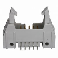
71922-110LF
Description
CONN HEADER 10POS DUAL R/A PCB
Manufacturer
FCI
Series
Quickie™, Basics+r
Type
PCB Plugr
Specifications of 71922-110LF
Contact Type
Male Pin
Connector Type
Header, Shrouded
Number Of Positions
10
Number Of Positions Loaded
All
Pitch
0.100" (2.54mm)
Number Of Rows
2
Row Spacing
0.100" (2.54mm)
Contact Mating Length
0.228" (5.80mm)
Mounting Type
Through Hole, Right Angle
Termination
Solder
Fastening Type
Latch Lock/Eject Hooks
Contact Finish
Gold, GXT™
Contact Finish Thickness
30µin (0.76µm)
Color
Gray
Product Type
Headers - Latch / Eject
Number Of Positions / Contacts
10
Mounting Style
Through Hole
Mounting Angle
Right
Termination Style
Solder
Contact Plating
Gold
Agency Approvals
CSA, UL
Angle
Right
Brand/series
Quickie®
Current, Rating
3 A
Flammability Rating
UL94V-0
Length, Overall
44.7 mm
Length, Pin
0.114 "
Material, Contact
Phosphor Bronze
Material, Housing
Thermoplastic
Mounting Hole Size
1.02, 2.8 "
Number Of Contacts
10
Pin Spacing
2.54 mm
Special Features
Eject Latch
Temperature, Operating
-65 to +125 °C
Voltage, Rating
1500 VAC
Lead Free Status / RoHS Status
Lead free / RoHS Compliant
Features
-
Lead Free Status / Rohs Status
Lead free / RoHS Compliant
Other names
609-1760


TITLE
Quickie™ Connector System
Copyright
Form E-3334
Rev E
FCI
3.7.2
3.7.3
3.7.4
Thermal Shock. After exposure of the mated connector to alternate periods of extreme
high and low temperature, there shall be no evidence of cracking or crazing of the
insulator or other physical damage to the connector; the dielectric withstanding voltage of
an unterminated connector shall be not less than 1,000 volts RMS, 60 Hz (see paragraph
3.5.5). The test shall be in accordance with MIL-STD-202, Method 107; the following
details shall apply:
(a) Test Condition - B (1 hour cycles)
(b) Temperature Range* - -65 to +105 o C
High Temperature Life. After exposure of the mated connector to a high temperature
operating environment, the insulation resistance of an unterminated connector shall be not
less than 100,000 megohms (see paragraph 3.5.4); the contact resistance of a terminated
connector shall not exceed 15 milliohms (see paragraph 3.5.2). The test shall be in
accordance with MIL-STD-202, Method 108; the following details shall apply:
(a) Test Chamber Temperature - 85 o C
(b) Test Condition (Duration)- B (250 hours)
(c) Operating Conditions - 1.0 ampere DC current (rated) through all contacts of
Shock. There shall be no evidence of physical or mechanical damage when the mated
connectors are subjected to transient accelerations. During and after each shock, the
contacts shall evidence no discontinuity greater than 1 microsecond. The test shall be in
accordance with MIL-STD-202, Method 213. The following details shall apply:
(a) Test Condition - I (l00G, 6ms sawtooth)
(b) Number of Shocks - 3 shocks in each direction along three orthogonal axes (18 total)
(c) Mounting - see Figure 5
terminated connector; duty cycle: 45 minutes ON and 15 minutes OFF.
TYPE
PRODUCT SPECIFICATION
PDM: Rev:F
STATUS:
NUMBER
PAGE
AUTHORIZED BY
CLASSIFICATION
M.Barrios
12 of 20
Released
BUS-12-082
UNRESTRICTED
Printed: Apr 13, 2007
REVISION
DATE
31 Jul 06
F
GS-01-001
.
Related parts for 71922-110LF
Image
Part Number
Description
Manufacturer
Datasheet
Request
R

Part Number:
Description:
CONN HEADER 10POS DUAL R/A PCB
Manufacturer:
FCI
Datasheet:
Part Number:
Description:
QKE III HDR RA GXT WL
Manufacturer:
FCI
Datasheet:
Part Number:
Description:
CONN HEADER 40POS DUAL R/A PCB
Manufacturer:
FCI
Datasheet:
Part Number:
Description:
CONN HEADER 50POS DUAL R/A PCB
Manufacturer:
FCI
Datasheet:

Part Number:
Description:
CONN HEADER 60POS DUAL R/A PCB
Manufacturer:
FCI
Datasheet:

Part Number:
Description:
PLUG, XLR, PANEL, BLACK, 4POLE
Manufacturer:
DELTRON
Datasheet:

Part Number:
Description:
CONNECTOR, XLR, PLUG, 3POS
Manufacturer:
DELTRON EMCON
Datasheet:

Part Number:
Description:
30485Fire Fighter Phone Accessories
Manufacturer:
GAMEWELL-FCI Gamewell-FCI by Honeywell
Datasheet:
Part Number:
Description:
Door, lock & key
Manufacturer:
GAMEWELL-FCI [Gamewell-FCI by Honeywell]
Datasheet:

Part Number:
Description:
Manufacturer:
FCI
Datasheet: