71922-110LF FCI, 71922-110LF Datasheet - Page 6
71922-110LF
Manufacturer Part Number
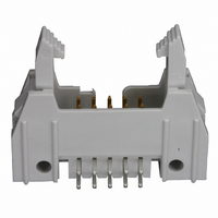
71922-110LF
Description
CONN HEADER 10POS DUAL R/A PCB
Manufacturer
FCI
Series
Quickie™, Basics+r
Type
PCB Plugr
Specifications of 71922-110LF
Contact Type
Male Pin
Connector Type
Header, Shrouded
Number Of Positions
10
Number Of Positions Loaded
All
Pitch
0.100" (2.54mm)
Number Of Rows
2
Row Spacing
0.100" (2.54mm)
Contact Mating Length
0.228" (5.80mm)
Mounting Type
Through Hole, Right Angle
Termination
Solder
Fastening Type
Latch Lock/Eject Hooks
Contact Finish
Gold, GXT™
Contact Finish Thickness
30µin (0.76µm)
Color
Gray
Product Type
Headers - Latch / Eject
Number Of Positions / Contacts
10
Mounting Style
Through Hole
Mounting Angle
Right
Termination Style
Solder
Contact Plating
Gold
Agency Approvals
CSA, UL
Angle
Right
Brand/series
Quickie®
Current, Rating
3 A
Flammability Rating
UL94V-0
Length, Overall
44.7 mm
Length, Pin
0.114 "
Material, Contact
Phosphor Bronze
Material, Housing
Thermoplastic
Mounting Hole Size
1.02, 2.8 "
Number Of Contacts
10
Pin Spacing
2.54 mm
Special Features
Eject Latch
Temperature, Operating
-65 to +125 °C
Voltage, Rating
1500 VAC
Lead Free Status / RoHS Status
Lead free / RoHS Compliant
Features
-
Lead Free Status / Rohs Status
Lead free / RoHS Compliant
Other names
609-1760


TITLE
Quickie™ Connector System
Copyright
Form E-3334
Rev E
FCI
The connector system shall be of two-piece design, consisting of: a molded, straight or right-angle,
shielded header having .64/0.025 diameter or .64/0.025 square header contacts arranged for printed
wiring board termination on a 2.54/0.100 square grid; and a multi-piece receptacle connector having
self-stripping contact terminations for flat, flexible, round conductor cable on a 1.27/0.050 inch center
and either one single-ended or two single-ended cantilever members for interfacing with the header
contact.
NOTE: While the receptacle connector will mate with any .64/0.025 diameter or .64/0.025 square
header contacts on an appropriate grid, performance of such a combination must be determined by
actual test. Minimum pin length is 4.32/.170", maximum pin length is 6.35/.250". Recommended pin
length is 5.84/.230".
3.4.1
3.4.2
3.4.3
3.4.4
Installation.
3.4.1.1
3.4.1.2
Latching Mechanism. An optional latching mechanism shall be available for locking the
plug into the receptacle to withstand service conditions without disconnecting.
Strain Relief. An optional strain relief shall be available to protect the receptacle
terminations against pull and flexing forces.
Polarizing Feature. An optional molded-in polarizing feature shall be available to insure
correct orientation of the receptacle connector and its mating header.
TYPE
PRODUCT SPECIFICATION
Header. The header shall mount on single- or double-sided or multi-
layered printed wiring board of any thickness to + .08/.003 inch (Size 4)
having .89/0.035 + 0.003 diameter holes (Round Pin) or 1.02/.040 +
.08/.003 diameter holes (square pin) on a 2.54/0.0100 square grid. The
termination layout shall be in accordance with the printed wiring
requirements of MIL-STD-275 and MIL-P-55110.
Receptacle. The receptacle shall simultaneously terminate up to 60 wires
size AWG #28 (stranded) or AWG #30 (solid) on 1.27/0.050 inch centers
without pre-stripping the PVC (polyvinylchloride) cable insulation. The
cable shall conform to the requirements of specifications BUS-12-001.
PDM: Rev:F
STATUS:
NUMBER
PAGE
AUTHORIZED BY
CLASSIFICATION
M.Barrios
6 of 20
Released
BUS-12-082
UNRESTRICTED
Printed: Apr 13, 2007
REVISION
DATE
31 Jul 06
F
GS-01-001
.
Related parts for 71922-110LF
Image
Part Number
Description
Manufacturer
Datasheet
Request
R

Part Number:
Description:
CONN HEADER 10POS DUAL R/A PCB
Manufacturer:
FCI
Datasheet:
Part Number:
Description:
QKE III HDR RA GXT WL
Manufacturer:
FCI
Datasheet:
Part Number:
Description:
CONN HEADER 40POS DUAL R/A PCB
Manufacturer:
FCI
Datasheet:
Part Number:
Description:
CONN HEADER 50POS DUAL R/A PCB
Manufacturer:
FCI
Datasheet:

Part Number:
Description:
CONN HEADER 60POS DUAL R/A PCB
Manufacturer:
FCI
Datasheet:

Part Number:
Description:
PLUG, XLR, PANEL, BLACK, 4POLE
Manufacturer:
DELTRON
Datasheet:

Part Number:
Description:
CONNECTOR, XLR, PLUG, 3POS
Manufacturer:
DELTRON EMCON
Datasheet:

Part Number:
Description:
30485Fire Fighter Phone Accessories
Manufacturer:
GAMEWELL-FCI Gamewell-FCI by Honeywell
Datasheet:
Part Number:
Description:
Door, lock & key
Manufacturer:
GAMEWELL-FCI [Gamewell-FCI by Honeywell]
Datasheet:

Part Number:
Description:
Manufacturer:
FCI
Datasheet: