PIC18F23K20-I/MV Microchip Technology, PIC18F23K20-I/MV Datasheet - Page 244
PIC18F23K20-I/MV
Manufacturer Part Number
PIC18F23K20-I/MV
Description
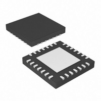
IC MCU 8BIT 8KB FLASH 28UQFN
Manufacturer
Microchip Technology
Series
PIC® XLP™ 18Fr
Specifications of PIC18F23K20-I/MV
Program Memory Type
FLASH
Program Memory Size
8KB (4K x 16)
Package / Case
28-UFQFN Exposed Pad
Core Processor
PIC
Core Size
8-Bit
Speed
64MHz
Connectivity
I²C, SPI, UART/USART
Peripherals
Brown-out Detect/Reset, HLVD, POR, PWM, WDT
Number Of I /o
24
Eeprom Size
256 x 8
Ram Size
512 x 8
Voltage - Supply (vcc/vdd)
1.8 V ~ 3.6 V
Data Converters
A/D 11x10b
Oscillator Type
Internal
Operating Temperature
-40°C ~ 85°C
Processor Series
PIC18F
Core
PIC
Data Bus Width
16 bit
Data Ram Size
768 B
Interface Type
MSSP, I2C, SPI, USART
Maximum Clock Frequency
64 MHz
Number Of Programmable I/os
25
Number Of Timers
4
Operating Supply Voltage
1.8 V to 3.6 V
Maximum Operating Temperature
+ 125 C
Mounting Style
SMD/SMT
3rd Party Development Tools
52715-96, 52716-328, 52717-734, 52712-325, EWPIC18
Development Tools By Supplier
PG164130, DV164035, DV244005, DV164005
Minimum Operating Temperature
- 40 C
On-chip Adc
10 bit, 10 Channel
A/d Bit Size
10 bit
A/d Channels Available
10
Lead Free Status / RoHS Status
Lead free / RoHS Compliant
Lead Free Status / RoHS Status
Lead free / RoHS Compliant, Lead free / RoHS Compliant
Available stocks
Company
Part Number
Manufacturer
Quantity
Price


PIC18F2XK20/4XK20
18.1.2.9
1.
2.
3.
4.
5.
6.
7.
8.
9.
10. Get the received 8 Least Significant data bits
11. If an overrun occurred, clear the OERR flag by
DS41303G-page 244
Initialize the SPBRGH:SPBRG register pair and
the BRGH and BRG16 bits to achieve the
desired baud rate (see Section 18.3 “EUSART
Baud Rate Generator (BRG)”).
Set the RX/DT and TX/CK TRIS controls to ‘1’.
Enable the serial port by setting the SPEN bit
and the RX/DT pin TRIS bit. The SYNC bit must
be clear for asynchronous operation.
If interrupts are desired, set the RCIE interrupt
enable bit and set the GIE and PEIE bits of the
INTCON register.
If 9-bit reception is desired, set the RX9 bit.
Set the DTRXP if inverted receive polarity is
desired.
Enable reception by setting the CREN bit.
The RCIF interrupt flag bit will be set when a
character is transferred from the RSR to the
receive buffer. An interrupt will be generated if
the RCIE interrupt enable bit was also set.
Read the RCSTA register to get the error flags
and, if 9-bit data reception is enabled, the ninth
data bit.
from the receive buffer by reading the RCREG
register.
clearing the CREN receiver enable bit.
Asynchronous Reception Set-up:
18.1.2.10
This mode would typically be used in RS-485 systems.
To set up an Asynchronous Reception with Address
Detect Enable:
1.
2.
3.
4.
5.
6.
7.
8.
9.
10. Read the RCSTA register to get the error flags.
11. Get the received 8 Least Significant data bits
12. If an overrun occurred, clear the OERR flag by
13. If the device has been addressed, clear the
Initialize the SPBRGH, SPBRG register pair and
the BRGH and BRG16 bits to achieve the
desired baud rate (see Section 18.3 “EUSART
Baud Rate Generator (BRG)”).
Set the RX/DT and TX/CK TRIS controls to ‘1’.
Enable the serial port by setting the SPEN bit.
The SYNC bit must be clear for asynchronous
operation.
If interrupts are desired, set the RCIE interrupt
enable bit and set the GIE and PEIE bits of the
INTCON register.
Enable 9-bit reception by setting the RX9 bit.
Enable address detection by setting the ADDEN
bit.
Set the DTRXP if inverted receive polarity is
desired.
Enable reception by setting the CREN bit.
The RCIF interrupt flag bit will be set when a
character with the ninth bit set is transferred
from the RSR to the receive buffer. An interrupt
will be generated if the RCIE interrupt enable bit
was also set.
The ninth data bit will always be set.
from the receive buffer by reading the RCREG
register. Software determines if this is the
device’s address.
clearing the CREN receiver enable bit.
ADDEN bit to allow all received data into the
receive buffer and generate interrupts.
9-bit Address Detection Mode Set-up
2010 Microchip Technology Inc.
Related parts for PIC18F23K20-I/MV
Image
Part Number
Description
Manufacturer
Datasheet
Request
R

Part Number:
Description:
Manufacturer:
Microchip Technology Inc.
Datasheet:
Part Number:
Description:
Manufacturer:
Microchip Technology Inc.
Datasheet:
Part Number:
Description:
Manufacturer:
Microchip Technology Inc.
Datasheet:
Part Number:
Description:
Manufacturer:
Microchip Technology Inc.
Datasheet:
Part Number:
Description:
Manufacturer:
Microchip Technology Inc.
Datasheet:
Part Number:
Description:
Manufacturer:
Microchip Technology Inc.
Datasheet:
Part Number:
Description:
Manufacturer:
Microchip Technology Inc.
Datasheet:
Part Number:
Description:
Manufacturer:
Microchip Technology Inc.
Datasheet: