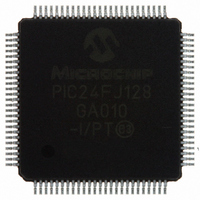
PIC24FJ128GA010-I/PT Microchip Technology, PIC24FJ128GA010-I/PT Datasheet - Page 100

PIC24FJ128GA010-I/PT
Manufacturer Part Number
PIC24FJ128GA010-I/PT
Description
IC PIC MCU FLASH 128K 100TQFP
Manufacturer
Microchip Technology
Series
PIC® 24Fr
Datasheets
1.PIC24FJ16GA002-ISS.pdf
(52 pages)
2.PIC24FJ64GA006-IPT.pdf
(240 pages)
3.PIC24FJ64GA006-IPT.pdf
(22 pages)
4.PIC24FJ128GA008-IPT.pdf
(12 pages)
5.PIC24FJ128GA006-IPT.pdf
(231 pages)
6.PIC24FJ128GA010-IPT.pdf
(230 pages)
Specifications of PIC24FJ128GA010-I/PT
Core Size
16-Bit
Program Memory Size
128KB (43K x 24)
Core Processor
PIC
Speed
16MHz
Connectivity
I²C, PMP, SPI, UART/USART
Peripherals
Brown-out Detect/Reset, POR, PWM, WDT
Number Of I /o
84
Program Memory Type
FLASH
Ram Size
8K x 8
Voltage - Supply (vcc/vdd)
2 V ~ 3.6 V
Data Converters
A/D 16x10b
Oscillator Type
Internal
Operating Temperature
-40°C ~ 85°C
Package / Case
100-TFQFP
Controller Family/series
PIC24
No. Of I/o's
84
Ram Memory Size
8KB
Cpu Speed
32MHz
No. Of Timers
5
No. Of Pwm Channels
5
Embedded Interface Type
EUART, I2C, PSP, SPI
Rohs Compliant
Yes
Processor Series
PIC24FJ
Core
PIC
Data Bus Width
16 bit
Data Ram Size
8 KB
Interface Type
SPI, I2C, USART
Maximum Clock Frequency
16 MHz
Number Of Programmable I/os
54
Number Of Timers
5
Maximum Operating Temperature
+ 85 C
Mounting Style
SMD/SMT
3rd Party Development Tools
52713-733, 52714-737, 53276-922, EWDSPIC
Development Tools By Supplier
PG164130, DV164035, DV244005, DV164005, PG164120, DM240001, DM240011
Minimum Operating Temperature
- 40 C
On-chip Adc
10 bit, 16 Channel
Package
100TQFP
Device Core
PIC
Family Name
PIC24
Maximum Speed
16 MHz
Operating Supply Voltage
2.5|3.3 V
Lead Free Status / RoHS Status
Lead free / RoHS Compliant
For Use With
DM240011 - KIT STARTER MPLAB FOR PIC24F MCUAC164333 - MODULE SKT FOR PM3 100QFPDV164033 - KIT START EXPLORER 16 MPLAB ICD2MA160011 - DAUGHTER BOARD PICDEM LCD 16F91XDM240001 - BOARD DEMO PIC24/DSPIC33/PIC32
Eeprom Size
-
Lead Free Status / Rohs Status
Details
Available stocks
Company
Part Number
Manufacturer
Quantity
Price
Company:
Part Number:
PIC24FJ128GA010-I/PT
Manufacturer:
Microchi
Quantity:
627
Company:
Part Number:
PIC24FJ128GA010-I/PT
Manufacturer:
MICROCHIP
Quantity:
212
Company:
Part Number:
PIC24FJ128GA010-I/PT
Manufacturer:
Microchip Technology
Quantity:
10 000
PIC24FJ128GA010 FAMILY
A recommended code sequence for a clock switch
includes the following:
1.
2.
3.
4.
5.
6.
7.
8.
The core sequence for unlocking the OSCCON register
and initiating a clock switch is shown in Example 7-1.
DS39747E-page 100
Disable interrupts during the OSCCON register
unlock and write sequence.
Execute the unlock sequence for the OSCCON
high byte, by writing 78h and 9Ah to
OSCCON<15:8>
instructions.
Write new oscillator source to the NOSC control
bits in the instruction immediately following the
unlock sequence.
Execute the unlock sequence for the OSCCON
low
OSCCON<7:0> in two back-to-back instructions.
Set the OSWEN bit in the instruction immediately
following the unlock sequence.
Continue to execute code that is not clock
sensitive (optional).
Invoke an appropriate amount of software delay
(cycle counting) to allow the selected oscillator
and/or PLL to start and stabilize.
Check to see if OSWEN is ‘0’. If it is, the switch
was successful. If OSWEN is still set, then
check the LOCK bit to determine cause of
failure.
byte
by
writing
in
46h
two
and
back-to-back
57h
to
EXAMPLE 7-1:
;Place the new oscillator selection in W0
;OSCCONH (high byte) Unlock Sequence
MOV
MOV
MOV
MOV.b
MOV.b
;Set new oscillator selection
MOV.b
;OSCCONL (low byte) unlock sequence
MOV
MOV
MOV
MOV.b
MOV.b
;Start oscillator switch operation
BSET OSCCON, #0
#OSCCONH, w1
#0x78, w2
#0x9A, w3
w2, [w1]
w3, [w1]
WREG, OSCCONH
#OSCCONL, w1
#0x46, w2
#0x57, w3
w2, [w1]
w3, [w1]
BASIC CODE SEQUENCE
FOR CLOCK SWITCHING
© 2009 Microchip Technology Inc.


