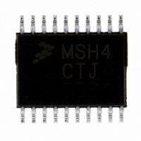
MC9S08SH4CTJ Freescale Semiconductor, MC9S08SH4CTJ Datasheet - Page 260

MC9S08SH4CTJ
Manufacturer Part Number
MC9S08SH4CTJ
Description
IC MCU 8BIT 4K FLASH 20-TSSOP
Manufacturer
Freescale Semiconductor
Series
HCS08r
Datasheet
1.MC9S08SH4CTJ.pdf
(338 pages)
Specifications of MC9S08SH4CTJ
Core Processor
HCS08
Core Size
8-Bit
Speed
40MHz
Connectivity
I²C, LIN, SCI, SPI
Peripherals
LVD, POR, PWM, WDT
Number Of I /o
17
Program Memory Size
4KB (4K x 8)
Program Memory Type
FLASH
Ram Size
256 x 8
Voltage - Supply (vcc/vdd)
2.7 V ~ 5.5 V
Data Converters
A/D 12x10b
Oscillator Type
Internal
Operating Temperature
-40°C ~ 85°C
Package / Case
20-TSSOP
Processor Series
S08SH
Core
HCS08
Data Bus Width
8 bit
Data Ram Size
256 B
Interface Type
SCI/SPI
Maximum Clock Frequency
40 MHz
Number Of Programmable I/os
17
Number Of Timers
3
Operating Supply Voltage
2.7 V to 5.5 V
Maximum Operating Temperature
+ 85 C
Mounting Style
SMD/SMT
3rd Party Development Tools
EWS08
Development Tools By Supplier
DEMO9S08SG32, DEMO9S08SG32AUTO, DEMO9S08SG8, DEMO9S08SG8AUTO, DEMO9S08SH32, DEMO9S08SH8
Minimum Operating Temperature
- 40 C
On-chip Adc
12-ch x 10-bit
A/d Bit Size
10 bit
A/d Channels Available
12
Height
1.05 mm
Length
6.6 mm
Supply Voltage (max)
5.5 V
Supply Voltage (min)
2.7 V
Width
4.5 mm
Lead Free Status / RoHS Status
Lead free / RoHS Compliant
Eeprom Size
-
Lead Free Status / Rohs Status
Lead free / RoHS Compliant
Available stocks
Company
Part Number
Manufacturer
Quantity
Price
Part Number:
MC9S08SH4CTJR
Manufacturer:
FREESCALE
Quantity:
20 000
- Current page: 260 of 338
- Download datasheet (4Mb)
Chapter 16 Timer/PWM Module (S08TPMV3)
16.5
16.5.1
The TPM is reset whenever any MCU reset occurs.
16.5.2
Reset clears the TPMxSC register which disables clocks to the TPM and disables timer overflow interrupts
(TOIE=0). CPWMS, MSnB, MSnA, ELSnB, and ELSnA are all cleared which configures all TPM
channels for input-capture operation with the associated pins disconnected from I/O pin logic (so all MCU
pins related to the TPM revert to general purpose I/O pins).
16.6
16.6.1
The TPM generates an optional interrupt for the main counter overflow and an interrupt for each channel.
The meaning of channel interrupts depends on each channel’s mode of operation. If the channel is
configured for input capture, the interrupt flag is set each time the selected input capture edge is
recognized. If the channel is configured for output compare or PWM modes, the interrupt flag is set each
time the main timer counter matches the value in the 16-bit channel value register.
All TPM interrupts are listed in
that can block the interrupt request from leaving the TPM and getting recognized by the separate interrupt
processing logic.
The TPM module will provide a high-true interrupt signal. Vectors and priorities are determined at chip
integration time in the interrupt module so refer to the user’s guide for the interrupt module or to the chip’s
complete documentation for details.
16.6.2
For each interrupt source in the TPM, a flag bit is set upon recognition of the interrupt condition such as
timer overflow, channel-input capture, or output-compare events. This flag may be read (polled) by
software to determine that the action has occurred, or an associated enable bit (TOIE or CHnIE) can be set
260
Reset Overview
Interrupts
General
Description of Reset Operation
General
Description of Interrupt Operation
Interrupt
CHnF
TOF
Enable
CHnIE
Local
TOIE
Table 16-9
MC9S08SH8 MCU Series Data Sheet, Rev. 3
Counter overflow
Channel event
Table 16-9. Interrupt Summary
Source
which shows the interrupt name, the name of any local enable
Set each time the timer counter reaches its terminal
count (at transition to next count value which is
usually 0x0000)
An input capture or output compare event took
place on channel n
Description
Freescale Semiconductor
Related parts for MC9S08SH4CTJ
Image
Part Number
Description
Manufacturer
Datasheet
Request
R
Part Number:
Description:
Manufacturer:
Freescale Semiconductor, Inc
Datasheet:
Part Number:
Description:
Manufacturer:
Freescale Semiconductor, Inc
Datasheet:
Part Number:
Description:
Manufacturer:
Freescale Semiconductor, Inc
Datasheet:
Part Number:
Description:
Manufacturer:
Freescale Semiconductor, Inc
Datasheet:
Part Number:
Description:
Manufacturer:
Freescale Semiconductor, Inc
Datasheet:
Part Number:
Description:
Manufacturer:
Freescale Semiconductor, Inc
Datasheet:
Part Number:
Description:
Manufacturer:
Freescale Semiconductor, Inc
Datasheet:
Part Number:
Description:
Manufacturer:
Freescale Semiconductor, Inc
Datasheet:
Part Number:
Description:
Manufacturer:
Freescale Semiconductor, Inc
Datasheet:
Part Number:
Description:
Manufacturer:
Freescale Semiconductor, Inc
Datasheet:
Part Number:
Description:
Manufacturer:
Freescale Semiconductor, Inc
Datasheet:
Part Number:
Description:
Manufacturer:
Freescale Semiconductor, Inc
Datasheet:
Part Number:
Description:
Manufacturer:
Freescale Semiconductor, Inc
Datasheet:
Part Number:
Description:
Manufacturer:
Freescale Semiconductor, Inc
Datasheet:
Part Number:
Description:
Manufacturer:
Freescale Semiconductor, Inc
Datasheet:


