PIC12C671/JW Microchip Technology, PIC12C671/JW Datasheet - Page 267
PIC12C671/JW
Manufacturer Part Number
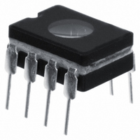
PIC12C671/JW
Description
IC MCU EPROM 1KX14 A/D 8CDIP
Manufacturer
Microchip Technology
Series
PIC® 12Cr
Datasheets
1.PIC16F688T-ISL.pdf
(688 pages)
2.PIC12CE673-10P.pdf
(129 pages)
3.PIC12CE673-10P.pdf
(14 pages)
Specifications of PIC12C671/JW
Core Processor
PIC
Core Size
8-Bit
Speed
10MHz
Peripherals
POR, WDT
Number Of I /o
5
Program Memory Size
1.75KB (1K x 14)
Program Memory Type
EPROM, UV
Ram Size
128 x 8
Voltage - Supply (vcc/vdd)
3 V ~ 5.5 V
Data Converters
A/D 4x8b
Oscillator Type
Internal
Operating Temperature
0°C ~ 70°C
Package / Case
8-CDIP (0.300", 7.62mm) Window
Lead Free Status / RoHS Status
Contains lead / RoHS non-compliant
Eeprom Size
-
Connectivity
-
Available stocks
Company
Part Number
Manufacturer
Quantity
Price

Part Number:
PIC12C671/JW
Manufacturer:
MICROCH
Quantity:
20 000


16.4.1
1997 Microchip Technology Inc.
Slave Mode
In slave mode, the SCL and SDA pins must be configured as inputs (TRIS bits set). The SSP
module will override the input state with the output data when required (slave-transmitter).
When an address is matched or the data transfer after an address match is received, the hard-
ware automatically will generate the acknowledge (ACK) pulse, and then load the SSPBUF reg-
ister with the received value currently in the SSPSR register.
There are certain conditions that will cause the SSP module not to give this ACK pulse. These
are if either (or both):
a)
b)
In this case, the SSPSR register value is not loaded into the SSPBUF, but bit SSPIF and SSPOV
bits are set.
tus of the BF and SSPOV bits. The shaded cells show the condition where user software did not
properly clear the overflow condition. The BF flag bit is cleared by reading the SSPBUF register
while the SSPOV bit is cleared through software.
The SCL clock input must have a minimum high and low time for proper operation. The high and
low times of the I
parameter 100
The buffer full bit, BF (SSPSTAT<0>), was set before the transfer was received.
The overflow bit, SSPOV (SSPCON<6>), was set before the transfer was received.
Table 16-2
and
2
C specification as well as the requirement of the SSP module are given in
parameter 101
shows what happens when a data transfer byte is received, given the sta-
of the
“Electrical Specifications”
Section 16. BSSP
section.
DS31016A-page 16-17
16
Related parts for PIC12C671/JW
Image
Part Number
Description
Manufacturer
Datasheet
Request
R

Part Number:
Description:
8-Pin/ 8-Bit CMOS Microcontroller with EEPROM Data Memory
Manufacturer:
Microchip Technology
Part Number:
Description:
IC, 8BIT MCU, PIC12, 32MHZ, DFN-8
Manufacturer:
Microchip Technology
Datasheet:
Part Number:
Description:
IC, 8BIT MCU, PIC12, 32MHZ, DFN-8
Manufacturer:
Microchip Technology
Datasheet:

Part Number:
Description:
Manufacturer:
Microchip Technology Inc.
Datasheet:
Part Number:
Description:
Manufacturer:
Microchip Technology Inc.
Datasheet:
Part Number:
Description:
Manufacturer:
Microchip Technology Inc.
Datasheet:
Part Number:
Description:
Manufacturer:
Microchip Technology Inc.
Datasheet:
Part Number:
Description:
Manufacturer:
Microchip Technology Inc.
Datasheet:
Part Number:
Description:
Manufacturer:
Microchip Technology Inc.
Datasheet:
Part Number:
Description:
Manufacturer:
Microchip Technology Inc.
Datasheet: