PIC12C671/JW Microchip Technology, PIC12C671/JW Datasheet - Page 399
PIC12C671/JW
Manufacturer Part Number
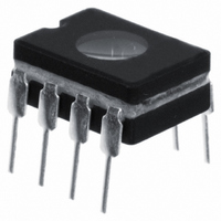
PIC12C671/JW
Description
IC MCU EPROM 1KX14 A/D 8CDIP
Manufacturer
Microchip Technology
Series
PIC® 12Cr
Datasheets
1.PIC16F688T-ISL.pdf
(688 pages)
2.PIC12CE673-10P.pdf
(129 pages)
3.PIC12CE673-10P.pdf
(14 pages)
Specifications of PIC12C671/JW
Core Processor
PIC
Core Size
8-Bit
Speed
10MHz
Peripherals
POR, WDT
Number Of I /o
5
Program Memory Size
1.75KB (1K x 14)
Program Memory Type
EPROM, UV
Ram Size
128 x 8
Voltage - Supply (vcc/vdd)
3 V ~ 5.5 V
Data Converters
A/D 4x8b
Oscillator Type
Internal
Operating Temperature
0°C ~ 70°C
Package / Case
8-CDIP (0.300", 7.62mm) Window
Lead Free Status / RoHS Status
Contains lead / RoHS non-compliant
Eeprom Size
-
Connectivity
-
Available stocks
Company
Part Number
Manufacturer
Quantity
Price

Part Number:
PIC12C671/JW
Manufacturer:
MICROCH
Quantity:
20 000


21.14
1997 Microchip Technology Inc.
Initialization
Example 21-4
Example 21-4:
;
;
;
;
Ensure that the required sampling time for the selected input
channel has elapsed. Then the conversion may be started.
BSF
CLRF
BSF
BCF
MOVLW
MOVWF
BCF
BSF
BSF
BSF
:
:
:
Section 21. 8-bit A/D Converter
shows the initialization of the A/D module for the PIC16C74A
STATUS, RP0
ADCON1
PIE1, ADIE
STATUS, RP0
0xC1
ADCON0
PIR1, ADIF
INTCON, PEIE
INTCON, GIE
ADCON0, GO
A/D Initialization (for PIC16C74A)
; Select Bank1
; Configure A/D inputs
; Enable A/D interrupts
; Select Bank0
; RC Clock, A/D is on, Channel 0 is selected
;
; Clear A/D interrupt flag bit
; Enable peripheral interrupts
; Enable all interrupts
; Start A/D Conversion
; The ADIF bit will be set and the GO/DONE
; bit is cleared upon completion of the
;
A/D Conversion.
DS31021A-page 21-15
21
Related parts for PIC12C671/JW
Image
Part Number
Description
Manufacturer
Datasheet
Request
R

Part Number:
Description:
8-Pin/ 8-Bit CMOS Microcontroller with EEPROM Data Memory
Manufacturer:
Microchip Technology
Part Number:
Description:
IC, 8BIT MCU, PIC12, 32MHZ, DFN-8
Manufacturer:
Microchip Technology
Datasheet:
Part Number:
Description:
IC, 8BIT MCU, PIC12, 32MHZ, DFN-8
Manufacturer:
Microchip Technology
Datasheet:

Part Number:
Description:
Manufacturer:
Microchip Technology Inc.
Datasheet:
Part Number:
Description:
Manufacturer:
Microchip Technology Inc.
Datasheet:
Part Number:
Description:
Manufacturer:
Microchip Technology Inc.
Datasheet:
Part Number:
Description:
Manufacturer:
Microchip Technology Inc.
Datasheet:
Part Number:
Description:
Manufacturer:
Microchip Technology Inc.
Datasheet:
Part Number:
Description:
Manufacturer:
Microchip Technology Inc.
Datasheet:
Part Number:
Description:
Manufacturer:
Microchip Technology Inc.
Datasheet: