PIC12C671/JW Microchip Technology, PIC12C671/JW Datasheet - Page 88
PIC12C671/JW
Manufacturer Part Number
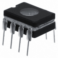
PIC12C671/JW
Description
IC MCU EPROM 1KX14 A/D 8CDIP
Manufacturer
Microchip Technology
Series
PIC® 12Cr
Datasheets
1.PIC16F688T-ISL.pdf
(688 pages)
2.PIC12CE673-10P.pdf
(129 pages)
3.PIC12CE673-10P.pdf
(14 pages)
Specifications of PIC12C671/JW
Core Processor
PIC
Core Size
8-Bit
Speed
10MHz
Peripherals
POR, WDT
Number Of I /o
5
Program Memory Size
1.75KB (1K x 14)
Program Memory Type
EPROM, UV
Ram Size
128 x 8
Voltage - Supply (vcc/vdd)
3 V ~ 5.5 V
Data Converters
A/D 4x8b
Oscillator Type
Internal
Operating Temperature
0°C ~ 70°C
Package / Case
8-CDIP (0.300", 7.62mm) Window
Lead Free Status / RoHS Status
Contains lead / RoHS non-compliant
Eeprom Size
-
Connectivity
-
Available stocks
Company
Part Number
Manufacturer
Quantity
Price

Part Number:
PIC12C671/JW
Manufacturer:
MICROCH
Quantity:
20 000


PICmicro MID-RANGE MCU FAMILY
5.6
DS31005A-page 5-6
STATUS Register
The STATUS register, shown in
status and the bank select bits for data memory. Since the selection of the Data Memory banks
is controlled by this register, it is required to be present in every bank. Also, this register is in the
same relative position (offset) in each bank (see
ory Organization”
The STATUS register can be the destination for any instruction, as with any other register. If the
STATUS register is the destination for an instruction that affects the Z, DC or C bits, then the write
to these three bits is disabled. These bits are set or cleared according to the device logic. Fur-
thermore, the TO and PD bits are not writable. Therefore, the result of an instruction with the
STATUS register as destination may be different than intended.
For example, CLRF STATUS will clear the upper-three bits and set the Z bit. This leaves the
STATUS register as 000u u1uu (where u = unchanged).
It is recommended, therefore, that only BCF, BSF, SWAPF and MOVWF instructions are used to
alter the STATUS register because these instructions do not affect the Z, C or DC bits from the
STATUS register. For other instructions, not affecting any status bits, see
Note 1: Some devices do not require the IRP and RP1 (STATUS<7:6>) bits. These bits are
Note 2: The C and DC bits operate as a borrow and digit borrow bit, respectively, in subtrac-
not used by the Section 5. CPU and ALU and should be maintained clear. Use of
these bits as general purpose R/W bits is NOT recommended, since this may affect
upward code compatibility with future products.
tion.
section).
Figure
5-1, contains the arithmetic status of the ALU, the RESET
Figure 6-5: “Register File Map”
1997 Microchip Technology Inc.
Table
5-1.
in the
“Mem-
Related parts for PIC12C671/JW
Image
Part Number
Description
Manufacturer
Datasheet
Request
R

Part Number:
Description:
8-Pin/ 8-Bit CMOS Microcontroller with EEPROM Data Memory
Manufacturer:
Microchip Technology
Part Number:
Description:
IC, 8BIT MCU, PIC12, 32MHZ, DFN-8
Manufacturer:
Microchip Technology
Datasheet:
Part Number:
Description:
IC, 8BIT MCU, PIC12, 32MHZ, DFN-8
Manufacturer:
Microchip Technology
Datasheet:

Part Number:
Description:
Manufacturer:
Microchip Technology Inc.
Datasheet:
Part Number:
Description:
Manufacturer:
Microchip Technology Inc.
Datasheet:
Part Number:
Description:
Manufacturer:
Microchip Technology Inc.
Datasheet:
Part Number:
Description:
Manufacturer:
Microchip Technology Inc.
Datasheet:
Part Number:
Description:
Manufacturer:
Microchip Technology Inc.
Datasheet:
Part Number:
Description:
Manufacturer:
Microchip Technology Inc.
Datasheet:
Part Number:
Description:
Manufacturer:
Microchip Technology Inc.
Datasheet: