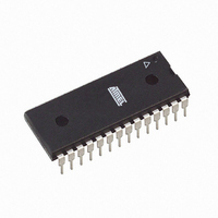
AT89LP828-20PU Atmel, AT89LP828-20PU Datasheet - Page 21

AT89LP828-20PU
Manufacturer Part Number
AT89LP828-20PU
Description
MCU 8051 8K FLASH SPI 28PDIP
Manufacturer
Atmel
Series
89LPr
Datasheet
1.AT89LP428-20AU.pdf
(149 pages)
Specifications of AT89LP828-20PU
Core Processor
8051
Core Size
8-Bit
Speed
20MHz
Connectivity
SPI, UART/USART
Peripherals
Brown-out Detect/Reset, POR, PWM, WDT
Number Of I /o
30
Program Memory Size
8KB (8K x 8)
Program Memory Type
FLASH
Eeprom Size
1K x 8
Ram Size
768 x 8
Voltage - Supply (vcc/vdd)
2.4 V ~ 5.5 V
Oscillator Type
Internal
Operating Temperature
-40°C ~ 85°C
Package / Case
28-DIP (0.300", 7.62mm)
Processor Series
AT89x
Core
8051
Data Bus Width
8 bit
Data Ram Size
768 B
Interface Type
2-Wire, SPI
Maximum Clock Frequency
20 MHz
Number Of Programmable I/os
30
Number Of Timers
3
Maximum Operating Temperature
+ 85 C
Mounting Style
Through Hole
3rd Party Development Tools
PK51, CA51, A51, ULINK2
Development Tools By Supplier
AT89ISP
Minimum Operating Temperature
- 40 C
Lead Free Status / RoHS Status
Lead free / RoHS Compliant
Data Converters
-
Lead Free Status / Rohs Status
Details
Available stocks
Company
Part Number
Manufacturer
Quantity
Price
Company:
Part Number:
AT89LP828-20PU
Manufacturer:
NXP
Quantity:
3 942
6.1
6.2
3654A–MICRO–8/09
Crystal Oscillator
External Clock Source
When enabled, the internal inverting oscillator amplifier is connected between XTAL1 and
XTAL2 for connection to an external quartz crystal or ceramic resonator. The oscillator may
operate in either high-speed or low-speed mode. Low-speed mode is intended for 32.768 kHz
watch crystals and consumes less power than high-speed mode. The configuration as shown in
Figure 6-1
device adds about 10 pF of capacitance to both XTAL1 and XTAL2, so that in some cases an
external capacitor may NOT be required. It is recommended that a resistor R1 be connected to
XTAL1, instead of load capacitor C1, for improved startup performance. The total capacitance
on XTAL1 or XTAL2, including the external load capacitor plus internal device load, board trace
and crystal loadings, should not exceed 20 pF.When using the crystal oscillator, P4.0 and P4.1
will have their inputs and outputs disabled. Also, XTAL2 in crystal oscillator mode should not be
used to directly drive a board-level clock without a buffer.
Figure 6-1.
Note:
The external clock option disables the oscillator amplifier and allows XTAL1 to be driven directly
by an external clock source as shown in
general-purpose I/O P4.1, or configured to output a divided version of the system clock.
Figure 6-2.
1. C2
applies for both high and low speed oscillators. Note that the internal structure of the
R1
Crystal Oscillator Connections
External Clock Drive Configuration
= 0–10 pF for Crystals
= 0–10 pF for Ceramic Resonators
= 4–5 MΩ
NC, GPIO, or
CLKOUT
Oscillator
External
Signal
C2
R1
Figure
6-2. XTAL2 may be left unconnected, used as
XTAL2 (P4.1)
XTAL1 (P4.0)
GND
~10 pF
~10 pF
AT89LP428/828
21


