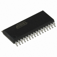
AT90PWM3B-16SUR Atmel, AT90PWM3B-16SUR Datasheet - Page 280

AT90PWM3B-16SUR
Manufacturer Part Number
AT90PWM3B-16SUR
Description
MCU AVR 8K FLASH 16MHA 32SOIC
Manufacturer
Atmel
Series
AVR® 90PWM Lightingr
Datasheet
1.AT90PWM3B-16SU.pdf
(361 pages)
Specifications of AT90PWM3B-16SUR
Core Processor
AVR
Core Size
8-Bit
Speed
16MHz
Connectivity
SPI, UART/USART
Peripherals
Brown-out Detect/Reset, POR, PWM, WDT
Number Of I /o
27
Program Memory Size
8KB (8K x 8)
Program Memory Type
FLASH
Eeprom Size
512 x 8
Ram Size
512 x 8
Voltage - Supply (vcc/vdd)
2.7 V ~ 5.5 V
Data Converters
A/D 11x10b; D/A 1x10b
Oscillator Type
Internal
Operating Temperature
-40°C ~ 105°C
Package / Case
32-SOIC (7.5mm Width)
Lead Free Status / RoHS Status
Lead free / RoHS Compliant
- Current page: 280 of 361
- Download datasheet (7Mb)
25.2
25.3
280
Fuse Bits
PSC Output Behaviour During Reset
AT90PWM2/3/2B/3B
The AT90PWM2/2B/3/3B has three Fuse bytes.
functionality of all the fuses and how they are mapped into the Fuse bytes. Note that the fuses
are read as logical zero, “0”, if they are programmed.
Table 25-4.
Note:
For external component safety reason, the state of PSC outputs during Reset can be pro-
grammed by fuses PSCRV, PSC0RB, PSC1RB & PSC2RB.
These fuses are located in the Extended Fuse Byte ( see
PSCRV gives the state low or high which will be forced on PSC outputs selected by PSC0RB,
PSC1RB & PSC2RB fuses.
If PSCRV fuse equals 0 (programmed), the selected PSC outputs will be forced to low state. If
PSCRV fuse equals 1 (unprogrammed), the selected PSC outputs will be forced to high state.
If PSC0RB fuse equals 1 (unprogrammed), PSCOUT00 & PSCOUT01 keep a standard port
behaviour. If PSC0RB fuse equals 0 (programmed), PSCOUT00 & PSCOUT01 are forced at
reset to low level or high level according to PSCRV fuse bit. In this second case, PSCOUT00 &
PSCOUT01 keep the forced state until PSOC0 register is written..
If PSC1RB fuse equals 1 (unprogrammed), PSCOUT10 & PSCOUT11 keep a standard port
behaviour. If PSC1RB fuse equals 0 (programmed), PSCOUT10 & PSCOUT11 are forced at
reset to low level or high level according to PSCRV fuse bit. In this second case, PSCOUT10 &
PSCOUT11 keep the forced state until PSOC1 register is written.
If PSC2RB fuse equals 1 (unprogrammed), PSCOUT20, PSCOUT21, PSCOUT22 &
PSCOUT23 keep a standard port behaviour. If PSC1RB fuse equals 0 (programmed),
PSCOUT20, PSCOUT21, PSCOUT22 & PSCOUT23 are forced at reset to low level or high
level according to PSCRV fuse bit. In this second case, PSCOUT20, PSCOUT21, PSCOUT22 &
PSCOUT23 keep the forced state until PSOC2 register is written.
Extended Fuse Byte
PSC2RB
PSC1RB
PSC0RB
PSCRV
–
BOOTSZ1
BOOTSZ0
BOOTRST
1. The default value of BOOTSZ1..0 results in maximum Boot Size. See
for details.
Extended Fuse Byte
Bit No
4
3
2
1
0
7
6
5
Description
PSC2 Reset Behaviour
PSC1 Reset Behaviour
PSC0 Reset Behaviour
PSCOUT Reset Value
–
Select Boot Size
(see Table 113 for details)
Select Boot Size
(see Table 113 for details)
Select Reset Vector
Table 25-4
Table
-
Table 25-6
25-4)
Default Value
1
1
1
1
1
0 (programmed)
0 (programmed)
1 (unprogrammed)
Table 25-7 on page 283
describe briefly the
(1)
(1)
4317J–AVR–08/10
Related parts for AT90PWM3B-16SUR
Image
Part Number
Description
Manufacturer
Datasheet
Request
R

Part Number:
Description:
Manufacturer:
Atmel Corporation
Datasheet:

Part Number:
Description:
IC MCU AVR RISC 8K FLASH 32-SOIC
Manufacturer:
Atmel
Datasheet:

Part Number:
Description:
IC MCU AVR RISC 8K FLASH 32-QFN
Manufacturer:
Atmel
Datasheet:

Part Number:
Description:
IC AVR MCU FLASH 8K 32QFN
Manufacturer:
Atmel
Datasheet:

Part Number:
Description:
IC AVR MCU FLASH 8K 32SOIC
Manufacturer:
Atmel
Datasheet:

Part Number:
Description:
MCU AVR 8K FLASH 16MHZ 32-QFN
Manufacturer:
Atmel
Datasheet:

Part Number:
Description:
DEV KIT FOR AVR/AVR32
Manufacturer:
Atmel
Datasheet:

Part Number:
Description:
INTERVAL AND WIPE/WASH WIPER CONTROL IC WITH DELAY
Manufacturer:
ATMEL Corporation
Datasheet:

Part Number:
Description:
Low-Voltage Voice-Switched IC for Hands-Free Operation
Manufacturer:
ATMEL Corporation
Datasheet:

Part Number:
Description:
MONOLITHIC INTEGRATED FEATUREPHONE CIRCUIT
Manufacturer:
ATMEL Corporation
Datasheet:

Part Number:
Description:
AM-FM Receiver IC U4255BM-M
Manufacturer:
ATMEL Corporation
Datasheet:

Part Number:
Description:
Monolithic Integrated Feature Phone Circuit
Manufacturer:
ATMEL Corporation
Datasheet:

Part Number:
Description:
Multistandard Video-IF and Quasi Parallel Sound Processing
Manufacturer:
ATMEL Corporation
Datasheet:


