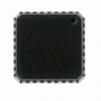
ATTINY26L-8MU Atmel, ATTINY26L-8MU Datasheet - Page 39

ATTINY26L-8MU
Manufacturer Part Number
ATTINY26L-8MU
Description
ID MCU AVR 2K 5V 8MHZ 32-QFN
Manufacturer
Atmel
Series
AVR® ATtinyr
Specifications of ATTINY26L-8MU
Core Processor
AVR
Core Size
8-Bit
Speed
8MHz
Connectivity
USI
Peripherals
Brown-out Detect/Reset, POR, PWM, WDT
Number Of I /o
16
Program Memory Size
2KB (1K x 16)
Program Memory Type
FLASH
Eeprom Size
128 x 8
Ram Size
128 x 8
Voltage - Supply (vcc/vdd)
2.7 V ~ 5.5 V
Data Converters
A/D 11x10b
Oscillator Type
Internal
Operating Temperature
-40°C ~ 85°C
Package / Case
32-VQFN Exposed Pad, 32-HVQFN, 32-SQFN, 32-DHVQFN
Processor Series
ATTINY2x
Core
AVR8
Data Bus Width
8 bit
Data Ram Size
128 B
Interface Type
2-Wire, ISP, SM-Bus, SPI, UART, USI
Maximum Clock Frequency
8 MHz
Number Of Programmable I/os
16
Number Of Timers
2
Operating Supply Voltage
2.7 V to 5.5 V
Maximum Operating Temperature
+ 85 C
Mounting Style
SMD/SMT
3rd Party Development Tools
EWAVR, EWAVR-BL
Development Tools By Supplier
ATAVRDRAGON, ATSTK500, ATSTK600, ATAVRISP2, ATAVRONEKIT
Minimum Operating Temperature
- 40 C
On-chip Adc
10 bit, 11 Channel
Cpu Family
ATtiny
Device Core
AVR
Device Core Size
8b
Frequency (max)
8MHz
Total Internal Ram Size
128Byte
# I/os (max)
16
Number Of Timers - General Purpose
2
Operating Supply Voltage (typ)
3.3/5V
Operating Supply Voltage (max)
5.5V
Operating Supply Voltage (min)
2.7V
Instruction Set Architecture
RISC
Operating Temp Range
-40C to 85C
Operating Temperature Classification
Industrial
Mounting
Surface Mount
Pin Count
32
Package Type
MLF EP
For Use With
ATSTK600 - DEV KIT FOR AVR/AVR32770-1007 - ISP 4PORT ATMEL AVR MCU SPI/JTAGATAVRISP2 - PROGRAMMER AVR IN SYSTEMATSTK505 - ADAPTER KIT FOR 14PIN AVR MCU
Lead Free Status / RoHS Status
Lead free / RoHS Compliant
Other names
ATTINY26L-8MJ
ATTINY26L-8MJ
ATTINY26L-8MJ
Available stocks
Company
Part Number
Manufacturer
Quantity
Price
Part Number:
ATTINY26L-8MU
Manufacturer:
ATMEL/爱特梅尔
Quantity:
20 000
Standby Mode
Table 19. Active Clock Domains and Wake-up Sources in the different Sleep Modes.
Notes:
1477K–AVR–08/10
Sleep Mode
Idle
ADC Noise
Reduction
Power-down
Standby
1. Only recommended with external crystal or resonator selected as clock source.
2. Only level interrupt INT0.
(1)
clk
CPU
Active Clock domains
clk
FLASH
If the wake-up condition disappears before the MCU wakes up and starts to execute, e.g., a low
level on INT0 is not held long enough, the interrupt causing the wake-up will not be executed.
When the SM1..0 bits are “11” and an External Crystal/Resonator clock option is selected, the
SLEEP instruction forces the MCU into the Standby mode. This mode is identical to Power-down
with the exception that the Oscillator is kept running. From Standby mode, the device wakes up
in only six clock cycles.
clk
X
IO
clk
X
X
ADC
Source Enabled
Oscillators
Main Clock
X
X
X
INT0, and Pin
Change
X
X
X
X
(2)
(2)
(2)
Condition
USI Start
X
X
X
X
Wake-up Sources
EEPROM
Ready
X
X
ADC
X
X
Other I/O
X
39


