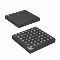
ATXMEGA32A4-CU Atmel, ATXMEGA32A4-CU Datasheet - Page 342

ATXMEGA32A4-CU
Manufacturer Part Number
ATXMEGA32A4-CU
Description
MCU AVR 32+4 FLASH 49VFBGA
Manufacturer
Atmel
Series
AVR® XMEGAr
Specifications of ATXMEGA32A4-CU
Core Processor
AVR
Core Size
8/16-Bit
Speed
32MHz
Connectivity
I²C, IrDA, SPI, UART/USART
Peripherals
Brown-out Detect/Reset, DMA, POR, PWM, WDT
Number Of I /o
34
Program Memory Size
32KB (16K x 16)
Program Memory Type
FLASH
Eeprom Size
2K x 8
Ram Size
4K x 8
Voltage - Supply (vcc/vdd)
1.6 V ~ 3.6 V
Data Converters
A/D 12x12b, D/A 2x12b
Oscillator Type
Internal
Operating Temperature
-40°C ~ 85°C
Package / Case
49-VFBGA
Processor Series
ATXMEGA32x
Core
AVR8
Data Bus Width
8 bit, 16 bit
Data Ram Size
4 KB
Interface Type
I2C, SPI, USART
Maximum Clock Frequency
32 MHz
Number Of Programmable I/os
36
Number Of Timers
5
Operating Supply Voltage
1.6 V to 3.6 V
Maximum Operating Temperature
+ 85 C
Mounting Style
SMD/SMT
3rd Party Development Tools
EWAVR, EWAVR-BL
Development Tools By Supplier
ATAVRDRAGON, ATAVRISP2, ATAVRONEKIT
Minimum Operating Temperature
- 40 C
On-chip Adc
12 bit, 1 Channel
On-chip Dac
2 bit, 1 Channel
For Use With
ATAVRONEKIT - KIT AVR/AVR32 DEBUGGER/PROGRMMRATSTK600 - DEV KIT FOR AVR/AVR32770-1007 - ISP 4PORT ATMEL AVR MCU SPI/JTAG770-1004 - ISP 4PORT FOR ATMEL AVR MCU SPI
Lead Free Status / RoHS Status
Lead free / RoHS Compliant
Available stocks
Company
Part Number
Manufacturer
Quantity
Price
- Current page: 342 of 445
- Download datasheet (6Mb)
28.5.2
28.5.2.1
28.5.2.2
28.5.2.3
28.5.3
28.5.4
28.6
28.6.1
8077H–AVR–12/09
Boundary-scan chain
Device Identification register
Boundary-scan Chain
PDICOM data register
Scanning the Port Pins
Version
Part Number
Manufacturer ID
Figure 28-3. Device Identification register
Version is a 4-bit number identifying the revision of the component. The JTAG version number
follows the revision of the device. Revision A is 0x0, revision B is 0x1 and so on.
The part number is a 16-bit code identifying the component. Refer to the device data sheets to
find the correct number.
The Manufacturer ID is an 11-bit code identifying the manufacturer. For Atmel this code is
11x01F.
The Boundary-scan Chain has the capability of driving and observing the logic levels on all I/O
pins. Refer to
The PDICOM data register is a 9-bit wide register used for serial-to-parallel - and parallel-to-
serial conversion of data between the JTAG TAP and the PDI. For details refer to
”Program and Debug Interface” on page
The Boundary-scan chain has the capability of driving and observing the logic levels on the I/O
pins. To ensure a predictable chip behavior during and after the instructions EXTEST, CLAMP
and HIGHZ, the chip is automatically put in reset. During active reset, the external oscillators,
analog modules, and non-default port settings (like pull-up/down, bus-keeper, wired-AND/-OR)
are disabled. It should be noted that the current chip - and port state is unaffected by the SAM-
PLE and PRELOAD instructions.
Figure 28-4 on page 343
This cell is able to control and observe both pin direction and pin value via a two-stage Shift
Register. When no alternate port function is present, Output control corresponds to the DIR reg-
ister value, Output data corresponds to the OUT register value, and Input data corresponds to
the IN register value (tapped before the input inverter and - synchronizer). Mode represents
either an active CLAMP or EXTEST instruction, while ShiftDR is set when the TAP controller is
in its Shift-DR state.
Bit
Device ID
Section 28.6 ”Boundary-scan chain” on page 342
MSB
31
Version
4 bits
28
shows the Boundary-scan Cell used for all the bi-directional port pins.
27
344.
Part Number
16 bits
12
for a complete description.
11
Manufacturer ID
11 bits
XMEGA A
1
Section 29.
LSB
1 bit
0
1
342
Related parts for ATXMEGA32A4-CU
Image
Part Number
Description
Manufacturer
Datasheet
Request
R

Part Number:
Description:
DEV KIT FOR AVR/AVR32
Manufacturer:
Atmel
Datasheet:

Part Number:
Description:
INTERVAL AND WIPE/WASH WIPER CONTROL IC WITH DELAY
Manufacturer:
ATMEL Corporation
Datasheet:

Part Number:
Description:
Low-Voltage Voice-Switched IC for Hands-Free Operation
Manufacturer:
ATMEL Corporation
Datasheet:

Part Number:
Description:
MONOLITHIC INTEGRATED FEATUREPHONE CIRCUIT
Manufacturer:
ATMEL Corporation
Datasheet:

Part Number:
Description:
AM-FM Receiver IC U4255BM-M
Manufacturer:
ATMEL Corporation
Datasheet:

Part Number:
Description:
Monolithic Integrated Feature Phone Circuit
Manufacturer:
ATMEL Corporation
Datasheet:

Part Number:
Description:
Multistandard Video-IF and Quasi Parallel Sound Processing
Manufacturer:
ATMEL Corporation
Datasheet:

Part Number:
Description:
High-performance EE PLD
Manufacturer:
ATMEL Corporation
Datasheet:

Part Number:
Description:
8-bit Flash Microcontroller
Manufacturer:
ATMEL Corporation
Datasheet:

Part Number:
Description:
2-Wire Serial EEPROM
Manufacturer:
ATMEL Corporation
Datasheet:


