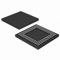
LPC2880FET180,551 NXP Semiconductors, LPC2880FET180,551 Datasheet - Page 22

LPC2880FET180,551
Manufacturer Part Number
LPC2880FET180,551
Description
IC ARM7 MCU RAM 16K 180TFBGA
Manufacturer
NXP Semiconductors
Series
LPC2800r
Datasheet
1.LPC2880FET180551.pdf
(43 pages)
Specifications of LPC2880FET180,551
Core Processor
ARM7
Core Size
16/32-Bit
Speed
60MHz
Connectivity
EBI/EMI, I²C, IrDA, MMC, UART/USART, USB
Peripherals
DMA, I²S, LCD, WDT
Number Of I /o
85
Program Memory Type
ROMless
Ram Size
64K x 8
Voltage - Supply (vcc/vdd)
1.7 V ~ 3.6 V
Data Converters
A/D 5x10b
Oscillator Type
External
Operating Temperature
-40°C ~ 85°C
Package / Case
180-TFBGA
Processor Series
LPC28
Core
ARM7TDMI-S
Data Bus Width
32 bit
Data Ram Size
64 KB
Interface Type
I2C, I2S, UART, USB
Maximum Clock Frequency
60 MHz
Number Of Programmable I/os
81
Number Of Timers
2
Operating Supply Voltage
3.3 V
Maximum Operating Temperature
+ 85 C
Mounting Style
SMD/SMT
3rd Party Development Tools
MDK-ARM, RL-ARM, ULINK2
Minimum Operating Temperature
- 40 C
On-chip Adc
10 bit, 5 Channel
For Use With
OM10092 - EVAL BOARD FOR LPC288X
Lead Free Status / RoHS Status
Lead free / RoHS Compliant
Eeprom Size
-
Program Memory Size
-
Lead Free Status / Rohs Status
Details
Other names
568-3245
935281368551
LPC2880FET180-S
935281368551
LPC2880FET180-S
Available stocks
Company
Part Number
Manufacturer
Quantity
Price
Company:
Part Number:
LPC2880FET180,551
Manufacturer:
NXP Semiconductors
Quantity:
10 000
NXP Semiconductors
LPC2880_LPC2888_3
Preliminary data sheet
6.18.1 Features
6.19.1 Features
6.19 SD/MMC card interface
The LPC2880/2888 USB controller enables 480 Mbit/s or 12 Mbit/s data exchange with a
USB host controller. It includes a USB controller, a DMA engine, and a USB 2.0 ATX
physical interface.
The USB controller consists of the protocol engine and buffer management blocks. It
includes an SRAM that is accessible to the DMA engine and to the processor via the
register interface.
The DMA engine is an AHB master, having direct access to all of ARM memory space but
particularly to on-chip RAM. Each USB endpoint that requires its data to be transferred via
DMA is allocated to a logical DMA channel in the DMA engine.
Endpoints with small packet sizes can be handled by software via registers in the USB
controller. In particular, Control Endpoint 0 is always handled in this way.
The SD and MCI is an interface between the APB and multimedia and/or secure digital
memory cards.
The interface provides all functions specific to the Secure Digital/MultiMedia memory
card, such as the clock generation unit, power management control, command, data
transfer, interrupt generation, and DMA request generation.
•
•
•
•
•
•
•
•
•
•
•
•
•
•
Fully compliant with USB 2.0 specification (Hi-Speed and Full-Speed).
8 logical endpoints = 16 physical endpoints.
Supports Control, Bulk, Interrupt and Isochronous endpoints.
Endpoint type selection by software.
Endpoint maximum packet size setting by software.
Supports SoftConnect feature (requires an external 1.5 k resistor between the
CONNECT pad and 3.3 V).
Supports bus-powered capability with low suspend current.
Two DMA channels, assignable to any of 4 physical endpoints.
Supports Burst data transfers on the AHB.
Supports Retry and Split transactions on the AHB.
Conformance to Multimedia Card Specification v2.11 .
Conformance to Secure Digital Memory Card Physical Layer Specification, v0.96 .
Use as a multimedia card bus or a secure digital memory card bus host. It can be
connected to several multimedia cards, or a single secure digital memory card.
DMA transfers are supported through the Simple DMA facility.
16/32-bit ARM microcontrollers with external memory interface
Rev. 03 — 17 April 2008
LPC2880; LPC2888
© NXP B.V. 2008. All rights reserved.
22 of 43


