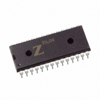
Z8F0823PJ005SG Zilog, Z8F0823PJ005SG Datasheet - Page 128

Z8F0823PJ005SG
Manufacturer Part Number
Z8F0823PJ005SG
Description
IC ENCORE MCU FLASH 8K 28-DIP
Manufacturer
Zilog
Series
Encore!® XP®r
Datasheet
1.Z8F0813PH005SC.pdf
(227 pages)
Specifications of Z8F0823PJ005SG
Core Processor
Z8
Core Size
8-Bit
Speed
5MHz
Connectivity
IrDA, UART/USART
Peripherals
Brown-out Detect/Reset, LED, POR, PWM, WDT
Number Of I /o
22
Program Memory Size
8KB (8K x 8)
Program Memory Type
FLASH
Ram Size
1K x 8
Voltage - Supply (vcc/vdd)
2.7 V ~ 3.6 V
Data Converters
A/D 8x10b
Oscillator Type
Internal
Operating Temperature
0°C ~ 70°C
Package / Case
28-DIP (0.600", 15.24mm)
Lead Free Status / RoHS Status
Lead free / RoHS Compliant
Eeprom Size
-
Other names
269-4218
Z8F0823PJ005SG
Z8F0823PJ005SG
- Current page: 128 of 227
- Download datasheet (3Mb)
PS025203-0405
Automatic Powerdown
Single-Shot Conversion
bits of resolution are lost because of a rounding error. As a result, the final value is an 11-
bit number.
If the ADC is idle (no conversions in progress) for 160 consecutive system clock cycles,
portions of the ADC are automatically powered down. From this powerdown state, the
ADC requires 40 system clock cycles to powerup. The ADC powers up when a conversion
is requested by the ADC Control register.
When configured for single-shot conversion, the ADC performs a single analog-to-digital
conversion on the selected analog input channel. After completion of the conversion, the
ADC shuts down. The steps for setting up the ADC and initiating a single-shot conversion
are as follows:
1. Enable the acceptable analog inputs by configuring the general-purpose I/O pins for
2. Write the
3. Write to the
4. CEN remains 1 while the conversion is in progress. A single-shot conversion requires
5. When the conversion is complete, the ADC control logic performs the following
alternate function. This configuration disables the digital input and output drivers.
–
The bit fields in the ADC Control register can be written simultaneously:
–
–
–
–
–
5129 system clock cycles to complete. If a single-shot conversion is requested from an
ADC powered-down state, the ADC uses 40 additional clock cycles to power-up
before beginning the 5129 cycle conversion.
operations:
Write the
voltage reference level or to disable the internal reference. The
contained in the
Write to the ANAIN[3:0] field to select from the available analog input sources
(different input pins available depending on the device)
Clear CONT to 0 to select a single-shot conversion.
If the internal voltage reference must be output to a pin, set the
The internal voltage reference must be enabled in this case.
Write the REFSELL bit of the pair {
voltage reference level or to disable the internal reference. The REFSELL bit is
contained in the
Set CEN to 1 to start the conversion.
ADC Control/Status Register 1
ADC Control Register 0
REFSELH
ADC Control/Status Register 1
ADC Control Register 0
P R E L I M I N A R Y
bit of the pair {
to configure the ADC and begin the conversion.
REFSELH
to configure the ADC
REFSELH
.
,
,
REFSELL
.
REFSELL
Z8 Encore!
} to select the internal
Product Specification
} to select the internal
Analog-to-Digital Converter
®
REFSELH
REFEXT
Z8F0823 Series
bit to 1.
bit is
111
Related parts for Z8F0823PJ005SG
Image
Part Number
Description
Manufacturer
Datasheet
Request
R

Part Number:
Description:
Communication Controllers, ZILOG INTELLIGENT PERIPHERAL CONTROLLER (ZIP)
Manufacturer:
Zilog, Inc.
Datasheet:

Part Number:
Description:
KIT DEV FOR Z8 ENCORE 16K TO 64K
Manufacturer:
Zilog
Datasheet:

Part Number:
Description:
KIT DEV Z8 ENCORE XP 28-PIN
Manufacturer:
Zilog
Datasheet:

Part Number:
Description:
DEV KIT FOR Z8 ENCORE 8K/4K
Manufacturer:
Zilog
Datasheet:

Part Number:
Description:
KIT DEV Z8 ENCORE XP 28-PIN
Manufacturer:
Zilog
Datasheet:

Part Number:
Description:
DEV KIT FOR Z8 ENCORE 4K TO 8K
Manufacturer:
Zilog
Datasheet:

Part Number:
Description:
CMOS Z8 microcontroller. ROM 16 Kbytes, RAM 256 bytes, speed 16 MHz, 32 lines I/O, 3.0V to 5.5V
Manufacturer:
Zilog, Inc.
Datasheet:

Part Number:
Description:
Low-cost microcontroller. 512 bytes ROM, 61 bytes RAM, 8 MHz
Manufacturer:
Zilog, Inc.
Datasheet:

Part Number:
Description:
Z8 4K OTP Microcontroller
Manufacturer:
Zilog, Inc.
Datasheet:

Part Number:
Description:
CMOS SUPER8 ROMLESS MCU
Manufacturer:
Zilog, Inc.
Datasheet:

Part Number:
Description:
SL1866 CMOSZ8 OTP Microcontroller
Manufacturer:
Zilog, Inc.
Datasheet:

Part Number:
Description:
SL1866 CMOSZ8 OTP Microcontroller
Manufacturer:
Zilog, Inc.
Datasheet:

Part Number:
Description:
OTP (KB) = 1, RAM = 125, Speed = 12, I/O = 14, 8-bit Timers = 2, Comm Interfaces Other Features = Por, LV Protect, Voltage = 4.5-5.5V
Manufacturer:
Zilog, Inc.
Datasheet:

Part Number:
Description:
Manufacturer:
Zilog, Inc.
Datasheet:


