C8051F313-GMR Silicon Laboratories Inc, C8051F313-GMR Datasheet - Page 164
C8051F313-GMR
Manufacturer Part Number
C8051F313-GMR
Description
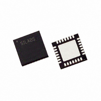
IC 8051 MCU 8K FLASH 28MLP
Manufacturer
Silicon Laboratories Inc
Series
C8051F31xr
Specifications of C8051F313-GMR
Core Processor
8051
Core Size
8-Bit
Speed
25MHz
Connectivity
SMBus (2-Wire/I²C), SPI, UART/USART
Peripherals
POR, PWM, Temp Sensor, WDT
Number Of I /o
25
Program Memory Size
8KB (8K x 8)
Program Memory Type
FLASH
Ram Size
1.25K x 8
Voltage - Supply (vcc/vdd)
2.7 V ~ 3.6 V
Data Converters
A/D 17x10b
Oscillator Type
Internal
Operating Temperature
-40°C ~ 85°C
Package / Case
28-VQFN Exposed Pad, 28-HVQFN, 28-SQFN, 28-DHVQFN
Lead Free Status / RoHS Status
Lead free / RoHS Compliant
Eeprom Size
-


C8051F310/1/2/3/4/5/6/7
15.1. Enhanced Baud Rate Generation
The UART0 baud rate is generated by Timer 1 in 8-bit auto-reload mode. The TX clock is generated by
TL1; the RX clock is generated by a copy of TL1 (shown as RX Timer in Figure 15.2), which is not user-
accessible. Both TX and RX Timer overflows are divided by two to generate the TX and RX baud rates.
The RX Timer runs when Timer 1 is enabled, and uses the same reload value (TH1). However, an
RX Timer reload is forced when a START condition is detected on the RX pin. This allows a receive to
begin any time a START is detected, independent of the TX Timer state.
Timer 1 should be configured for Mode 2, 8-bit auto-reload (see
ter/Timer with Auto-Reload” on page
occur at two times the desired UART baud rate frequency. Note that Timer 1 may be clocked by one of six
sources: SYSCLK, SYSCLK / 4, SYSCLK / 12, SYSCLK / 48, the external oscillator clock / 8, or an exter-
nal input T1. For any given Timer 1 clock source, the UART0 baud rate is determined by Equation 15.1.
Where T1
value). Timer 1 clock frequency is selected as described in
reference for typical baud rates and system clock frequencies is given in Table 15.1 through Table 15.6.
Note that the internal oscillator may still generate the system clock when the external oscillator is driving
Timer 1.
164
CLK
is the frequency of the clock supplied to Timer 1, and T1H is the high byte of Timer 1 (reload
Detected
Start
Figure 15.2. UART0 Baud Rate Logic
RX Timer
Equation 15.1. UART0 Baud Rate
UartBaudRate
Timer 1
TH1
TL1
189). The Timer 1 reload value should be set so that overflows will
Overflow
Overflow
Rev. 1.7
=
------------------------------ -
256 T1H
T1
–
Section “17. Timers” on page
CLK
2
2
Section “17.1.3. Mode 2: 8-bit Coun-
UART
1
-- -
2
RX Clock
TX Clock
187. A quick
Related parts for C8051F313-GMR
Image
Part Number
Description
Manufacturer
Datasheet
Request
R

Part Number:
Description:
SMD/C°/SINGLE-ENDED OUTPUT SILICON OSCILLATOR
Manufacturer:
Silicon Laboratories Inc
Part Number:
Description:
Manufacturer:
Silicon Laboratories Inc
Datasheet:
Part Number:
Description:
N/A N/A/SI4010 AES KEYFOB DEMO WITH LCD RX
Manufacturer:
Silicon Laboratories Inc
Datasheet:
Part Number:
Description:
N/A N/A/SI4010 SIMPLIFIED KEY FOB DEMO WITH LED RX
Manufacturer:
Silicon Laboratories Inc
Datasheet:
Part Number:
Description:
N/A/-40 TO 85 OC/EZLINK MODULE; F930/4432 HIGH BAND (REV E/B1)
Manufacturer:
Silicon Laboratories Inc
Part Number:
Description:
EZLink Module; F930/4432 Low Band (rev e/B1)
Manufacturer:
Silicon Laboratories Inc
Part Number:
Description:
I°/4460 10 DBM RADIO TEST CARD 434 MHZ
Manufacturer:
Silicon Laboratories Inc
Part Number:
Description:
I°/4461 14 DBM RADIO TEST CARD 868 MHZ
Manufacturer:
Silicon Laboratories Inc
Part Number:
Description:
I°/4463 20 DBM RFSWITCH RADIO TEST CARD 460 MHZ
Manufacturer:
Silicon Laboratories Inc
Part Number:
Description:
I°/4463 20 DBM RADIO TEST CARD 868 MHZ
Manufacturer:
Silicon Laboratories Inc
Part Number:
Description:
I°/4463 27 DBM RADIO TEST CARD 868 MHZ
Manufacturer:
Silicon Laboratories Inc
Part Number:
Description:
I°/4463 SKYWORKS 30 DBM RADIO TEST CARD 915 MHZ
Manufacturer:
Silicon Laboratories Inc
Part Number:
Description:
N/A N/A/-40 TO 85 OC/4463 RFMD 30 DBM RADIO TEST CARD 915 MHZ
Manufacturer:
Silicon Laboratories Inc
Part Number:
Description:
I°/4463 20 DBM RADIO TEST CARD 169 MHZ
Manufacturer:
Silicon Laboratories Inc