DF2117VT20V Renesas Electronics America, DF2117VT20V Datasheet - Page 652
DF2117VT20V
Manufacturer Part Number
DF2117VT20V
Description
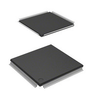
MCU 16BIT FLASH 3V 160K 144-TQFP
Manufacturer
Renesas Electronics America
Series
H8® H8S/2100r
Datasheet
1.DF2117VT20HV.pdf
(1040 pages)
Specifications of DF2117VT20V
Core Processor
H8S/2600
Core Size
16-Bit
Speed
20MHz
Connectivity
FIFO, I²C, LPC, SCI, SmartCard
Peripherals
POR, PWM, WDT
Number Of I /o
112
Program Memory Size
160KB (160K x 8)
Program Memory Type
FLASH
Ram Size
8K x 8
Voltage - Supply (vcc/vdd)
3 V ~ 3.6 V
Data Converters
A/D 16x10b
Oscillator Type
External
Operating Temperature
-20°C ~ 75°C
Package / Case
144-TQFP, 144-VQFP
Lead Free Status / RoHS Status
Lead free / RoHS Compliant
Eeprom Size
-
Available stocks
Company
Part Number
Manufacturer
Quantity
Price
Company:

Part Number:
DF2117VT20V
Manufacturer:
Renesas
Quantity:
100
Company:
Part Number:
DF2117VT20V
Manufacturer:
Renesas Electronics America
Quantity:
10 000


• Canceling software standby mode and watch mode
Rev. 2.00 Sep. 28, 2009 Page 610 of 994
REJ09B0452-0200
Software standby mode and watch mode are cancelled by a first KCLK falling interrupt. In this
case, an interrupt is generated at the first KCLK since software standby mode or watch mode
has been shifted (figure 19.17).
Notes on canceling operation are explained below.
⎯ When a transition to software standby mode or watch mode is performed while both
⎯ When software standby mode and watch mode are cancelled by a first KCLK falling
⎯ When software standby mode or watch mode is cancelled by receiving a receive clock, the
⎯ When transition to software standby mode or watch mode is made and the mode is
⎯ Priority of canceling software standby mode and watch mode is decided by the setting of
⎯ The interrupt signal path and flag setting of the first KCLK interrupt in normal operation
⎯ KCLK is input directly to the interrupt control block, not through the PS2, in software
KBIOE and KCIE are set to 1, canceling the current mode is enabled by a first KCLK
falling interrupt (the KBE and KBTS are not affected).
interrupt, the KCIF flag is not set (only the internal flag is set).
In the first KCLK interrupt handling routine, the KCIF bit is checked. If the KCIF is 0, it
indicates that the interrupt is generated after software standby mode and watch mode have
been cancelled.
reception is ignored. Execute reception terminating processing by an interrupt handing
routine, and then request retransfer.
canceled by a first KCLK falling interrupt during data transmission, state before
performing mode transition is held immediately after canceling the mode. Therefore,
initialization by an interrupt handling routine is required. Precautions as (b) and (c) which
are shown in figure 19.17 should be applied on interrupt generation.
ICR.
differ from those in software standby mode and watch mode. Figure 19.6 shows the
interrupt signal paths of the first KCLK interrupt.
Signal A: Interrupt signal in normal operation
Signal B: Interrupt signal in software standby mode and watch mode
standby mode and watch mode, and then an interrupt is generated by detection of a falling
edge. Therefore, the KCIF flag is not set. In this case, a flag that is in the interrupt control
block is set. The internal flag is automatically cleared after an interrupt request is sent to
the CPU. Figure 19.18 shows setting and clearing timing.
Related parts for DF2117VT20V
Image
Part Number
Description
Manufacturer
Datasheet
Request
R

Part Number:
Description:
0.6mm Pitch Board-to-Fine-Coaxial Cable Connectors
Manufacturer:
Hirose Electric
Datasheet:
Part Number:
Description:
0.6mm Pitch Board-to-fine-coaxial Cable Connectors
Manufacturer:
Hirose Electric
Datasheet:
Part Number:
Description:
0.6mm Pitch Board-to-fine-coaxial Cable Connectors
Manufacturer:
Hirose Electric
Datasheet:
Part Number:
Description:
Right angle, Two-piece for fine coaxial cable, Discrete wire connectors; HRS No: 687-0001-5 56; No. of Positions: 20; Connector Type: Board mounting; Contact Gender: Female; Contact Spacing (mm): 0.6; Terminal Pitch (mm): 0.6; PCB Mount Type: SMT; Cu
Manufacturer:
Hirose Electric
Part Number:
Description:
0.6mm Pitch Board-to-fine-coaxial Cable Connectors
Manufacturer:
Hirose Electric
Datasheet:
Part Number:
Description:
0.6mm Pitch Board-to-Fine-Coaxial Cable Connectors
Manufacturer:
HIROSE [Hirose Electric]
Datasheet:

Part Number:
Description:
KIT STARTER FOR M16C/29
Manufacturer:
Renesas Electronics America
Datasheet:

Part Number:
Description:
KIT STARTER FOR R8C/2D
Manufacturer:
Renesas Electronics America
Datasheet:

Part Number:
Description:
R0K33062P STARTER KIT
Manufacturer:
Renesas Electronics America
Datasheet:

Part Number:
Description:
KIT STARTER FOR R8C/23 E8A
Manufacturer:
Renesas Electronics America
Datasheet:

Part Number:
Description:
KIT STARTER FOR R8C/25
Manufacturer:
Renesas Electronics America
Datasheet:

Part Number:
Description:
KIT STARTER H8S2456 SHARPE DSPLY
Manufacturer:
Renesas Electronics America
Datasheet:

Part Number:
Description:
KIT STARTER FOR R8C38C
Manufacturer:
Renesas Electronics America
Datasheet:

Part Number:
Description:
KIT STARTER FOR R8C35C
Manufacturer:
Renesas Electronics America
Datasheet:

Part Number:
Description:
KIT STARTER FOR R8CL3AC+LCD APPS
Manufacturer:
Renesas Electronics America
Datasheet: