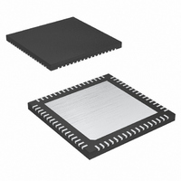
MAXQ2000-QAX+ Maxim Integrated Products, MAXQ2000-QAX+ Datasheet - Page 11

MAXQ2000-QAX+
Manufacturer Part Number
MAXQ2000-QAX+
Description
IC MCU 16BIT 32K FLASH 68-QFN
Manufacturer
Maxim Integrated Products
Series
MAXQ™r
Datasheet
1.MAXQ2000-RAX.pdf
(39 pages)
Specifications of MAXQ2000-QAX+
Core Processor
RISC
Core Size
16-Bit
Speed
20MHz
Connectivity
1-Wire, SPI, UART/USART
Peripherals
LCD, POR, PWM, WDT
Number Of I /o
50
Program Memory Size
64KB (32K x 16)
Program Memory Type
FLASH
Ram Size
2K x 8
Voltage - Supply (vcc/vdd)
1.8 V ~ 2.75 V
Oscillator Type
Internal
Operating Temperature
-40°C ~ 85°C
Package / Case
68-QFN Exposed Pad
Processor Series
MAXQ2000
Core
RISC
Data Bus Width
16 bit
Data Ram Size
2 KB
Interface Type
1-Wire, SPI, JTAG, UART
Maximum Clock Frequency
20 MHz
Number Of Programmable I/os
50
Number Of Timers
3
Operating Supply Voltage
1.8 V to 2.75 V
Maximum Operating Temperature
+ 85 C
Mounting Style
SMD/SMT
Development Tools By Supplier
MAXQ2000-KIT
Minimum Operating Temperature
- 40 C
Lead Free Status / RoHS Status
Lead free / RoHS Compliant
Eeprom Size
-
Data Converters
-
Lead Free Status / Rohs Status
Details
TQFN-EP
49–56
—
—
QFN-EP
58–65
PIN
—
—
1, 2, 12,
38, 44–
99, 100
13, 24,
25, 26,
35, 37,
49, 51,
55, 61,
72–75,
77–80,
87, 88,
89–96
LQFP
—
NAME
SEG0–
SEG7;
INT0–
P0.0–
P0.7;
INT3
N.C.
EP
____________________________________________________________________
Low-Power LCD Microcontroller
General-Purpose, Digital, I/O, Type-D Port; LCD Segment-Driver Output; External
Edge-Selectable Interrupt. This port functions as both bidirectional I/O pins and
LCD segment-drive outputs. All port pins are defaulted as input with weak pullup
after a reset. The port pads can be configured as an external interrupt for pins 7 to
4. If the external interrupt is enabled, the LCD function on the associated pin is
disabled. Setting the PCF0 bit enables the LCD for all pins on this port and disables
the general-purpose I/O function on all pins.
It is possible to mix the LCD and interrupt functions on the same port. To do this,
the interrupt enable must be established prior to setting the PCF0 bit. Care must be
taken not to enable the external interrupt while the LCD is in normal operational
mode, as this could result in potentially harmful contention between the LCD
controller output and the external source connected to the interrupt input.
No Connection. These pins should not be connected.
Exposed Paddle. Exposed paddle is on the under side of the package. It should be
left unconnected.
56-PIN
49
50
51
52
53
54
55
56
68-PIN
58
59
60
61
62
63
64
65
100-PIN
89
90
91
92
93
94
95
96
PORT
Pin Description (continued)
P0.0
P0.1
P0.2
P0.3
P0.4
P0.5
P0.6
P0.7
FUNCTION
SEG0
SEG1
SEG2
SEG3
SEG4
SEG5
SEG6
SEG7
ALTERNATE FUNCTIONS
INT0
INT1
INT2
INT3
—
—
—
—
11


