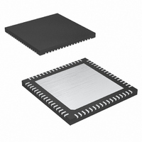
MAXQ2000-QAX+ Maxim Integrated Products, MAXQ2000-QAX+ Datasheet - Page 31

MAXQ2000-QAX+
Manufacturer Part Number
MAXQ2000-QAX+
Description
IC MCU 16BIT 32K FLASH 68-QFN
Manufacturer
Maxim Integrated Products
Series
MAXQ™r
Datasheet
1.MAXQ2000-RAX.pdf
(39 pages)
Specifications of MAXQ2000-QAX+
Core Processor
RISC
Core Size
16-Bit
Speed
20MHz
Connectivity
1-Wire, SPI, UART/USART
Peripherals
LCD, POR, PWM, WDT
Number Of I /o
50
Program Memory Size
64KB (32K x 16)
Program Memory Type
FLASH
Ram Size
2K x 8
Voltage - Supply (vcc/vdd)
1.8 V ~ 2.75 V
Oscillator Type
Internal
Operating Temperature
-40°C ~ 85°C
Package / Case
68-QFN Exposed Pad
Processor Series
MAXQ2000
Core
RISC
Data Bus Width
16 bit
Data Ram Size
2 KB
Interface Type
1-Wire, SPI, JTAG, UART
Maximum Clock Frequency
20 MHz
Number Of Programmable I/os
50
Number Of Timers
3
Operating Supply Voltage
1.8 V to 2.75 V
Maximum Operating Temperature
+ 85 C
Mounting Style
SMD/SMT
Development Tools By Supplier
MAXQ2000-KIT
Minimum Operating Temperature
- 40 C
Lead Free Status / RoHS Status
Lead free / RoHS Compliant
Eeprom Size
-
Data Converters
-
Lead Free Status / Rohs Status
Details
Embedded debugging capability is available through
the JTAG-compatible Test Access Port. Embedded
debug hardware and embedded ROM firmware pro-
vide in-circuit debugging capability to the user applica-
tion, eliminating the need for an expensive in-circuit
emulator. Figure 4 shows a block diagram of the in-cir-
cuit debugger. The in-circuit debug features include:
• a hardware debug engine,
• a set of registers able to set breakpoints on register,
• a set of debug service routines stored in the utility
The embedded hardware debug engine is an indepen-
dent hardware block in the microcontroller. The debug
engine can monitor internal activities and interact with
selected internal registers while the CPU is executing
user code. Collectively, the hardware and software fea-
tures allow two basic modes of in-circuit debugging:
• Background mode allows the host to configure and set
• Debug mode allows the debug engine to take control
Figure 4. In-Circuit Debugger
code, or data accesses, and
ROM.
up the in-circuit debugger while the CPU continues to
execute the application software at full speed. Debug
mode can be invoked from background mode.
of the CPU, providing read/write access to internal reg-
isters and memory, and single-step trace operation.
TMS
TCK
TDO
TDI
CONTROLLER
MAXQ2000
TAP
(UTILITY ROM)
ROUTINES
BREAKPOINT
In-Circuit Debug
SERVICE
DEBUG
DEBUG
ENGINE
CONTROL
ADDRESS
DATA
____________________________________________________________________
Low-Power LCD Microcontroller
CPU
The MAXQ2000 microcontroller incorporates an LCD
controller that interfaces to common low-voltage dis-
plays. By incorporating the LCD controller into the
microcontroller, the design requires only an LCD glass
rather than a considerably more expensive LCD mod-
ule. Every character in an LCD glass is composed of
one or more segments, each of which is activated by
selecting the appropriate segment and common signal.
The microcontroller can multiplex combinations of up to
33 segment (SEG0–SEG32) outputs and four common
signal outputs (COM0–COM3). Unused segment out-
puts can be used as general-purpose port pins.
The segments are easily addressed by writing to dedi-
cated display memory. Once the LCD controller set-
tings and display memory have been initialized, the
17-byte display memory is periodically scanned, and
the segment and common signals are generated auto-
matically at the selected display frequency. No addi-
tional processor overhead is required while the LCD
controller is running. Unused display memory can be
used for general-purpose storage.
The design is further simplified and cost-reduced by
the inclusion of software-adjustable internal voltage
dividers to control display contrast, using either V
or an external voltage. If desired, contrast can also be
controlled with an external resistance. The features of
the LCD controller include the following:
• Automatic LCD segment and common-drive signal
• Four display modes supported:
• Up to 36 segment outputs and four common-signal
• 17 bytes (136 bits) of display memory
• Flexible LCD clock source, selectable from 32kHz or
• Adjustable frame frequency
• Internal voltage-divider resistors eliminate require-
• Internal adjustable resistor allows contrast adjustment
generation
outputs
HFClk / 128
ment for external components
without external components
Static (COM0)
1/2 duty multiplexed with 1/2 bias voltages (COM0,
COM1)
1/3 duty multiplexed with 1/3 bias voltages (COM0,
COM1, COM2)
1/4 duty multiplexed with 1/3 bias voltages (COM0,
COM1, COM2, COM3)
LCD Controller
DDIO
31


