PIC12C672/JW Microchip Technology, PIC12C672/JW Datasheet - Page 490
PIC12C672/JW
Manufacturer Part Number
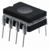
PIC12C672/JW
Description
IC MCU EPROM 2KX14 A/D 8CDIP
Manufacturer
Microchip Technology
Series
PIC® 12Cr
Datasheets
1.PIC16F688T-ISL.pdf
(688 pages)
2.PIC12CE673-10P.pdf
(129 pages)
3.PIC12CE673-10P.pdf
(14 pages)
Specifications of PIC12C672/JW
Core Processor
PIC
Core Size
8-Bit
Speed
10MHz
Peripherals
POR, WDT
Number Of I /o
5
Program Memory Size
3.5KB (2K x 14)
Program Memory Type
EPROM, UV
Ram Size
128 x 8
Voltage - Supply (vcc/vdd)
3 V ~ 5.5 V
Data Converters
A/D 4x8b
Oscillator Type
Internal
Operating Temperature
0°C ~ 70°C
Package / Case
8-CDIP (0.300", 7.62mm) Window
Lead Free Status / RoHS Status
Contains lead / RoHS non-compliant
Eeprom Size
-
Connectivity
-
Other names
Q395827
Available stocks
Company
Part Number
Manufacturer
Quantity
Price
Company:

Part Number:
PIC12C672/JW
Manufacturer:
MICKO
Quantity:
2 100


PICmicro MID-RANGE MCU FAMILY
26.3.1
26.3.2
DS31026A-page 26-6
Config. bits
OPTION_REG
Legend: Shaded cells are not used by the Watchdog Timer.
Name
WDT Period
WDT Programming Considerations
MPEEN
RBPU
Bit 7
The WDT has a nominal time-out period of 18 ms, (with no postscaler). The time-out period var-
ies with temperature, V
time-outs are desired, a postscaler with a division ratio of up to 1:128 can be assigned to the
WDT, under software control, by writing to the OPTION_REG register. Thus, time-out periods of
up to 2.3 seconds can be realized.
The
and prevent it from timing out and generating a device RESET.
The TO bit in the STATUS register will be cleared upon a Watchdog Timer time-out (WDT Reset
and WDT wake-up).
It should also be taken in account that under worst case conditions (V
ture = Maximum, maximum WDT postscaler) it may take several seconds before a WDT time-out
occurs.
Table 26-1: Summary of Watchdog Timer Registers
Note:
CLRWDT
INTEDG
BODEN
Bit 6
When the postscaler is assigned to the WDT, always execute a CLRWDT instruction
before changing the postscale value, otherwise a WDT reset may occur.
and
SLEEP
DD
instructions clear the WDT and the postscaler (if assigned to the WDT)
T0CS
Bit 5
CP1
and process variations from part to part (see DC specs). If longer
T0SE
Bit 4
CP0
PWRTE
Bit 3
PSA
WDTE
Bit 2
PS2
1997 Microchip Technology Inc.
DD
FOSC1
= Minimum, Tempera-
Bit 1
PS1
FOSC0
Bit 0
PS0
Related parts for PIC12C672/JW
Image
Part Number
Description
Manufacturer
Datasheet
Request
R

Part Number:
Description:
8-Pin/ 8-Bit CMOS Microcontroller with EEPROM Data Memory
Manufacturer:
Microchip Technology
Part Number:
Description:
IC, 8BIT MCU, PIC12, 32MHZ, DFN-8
Manufacturer:
Microchip Technology
Datasheet:
Part Number:
Description:
IC, 8BIT MCU, PIC12, 32MHZ, DFN-8
Manufacturer:
Microchip Technology
Datasheet:

Part Number:
Description:
Manufacturer:
Microchip Technology Inc.
Datasheet:
Part Number:
Description:
Manufacturer:
Microchip Technology Inc.
Datasheet:
Part Number:
Description:
Manufacturer:
Microchip Technology Inc.
Datasheet:
Part Number:
Description:
Manufacturer:
Microchip Technology Inc.
Datasheet:
Part Number:
Description:
Manufacturer:
Microchip Technology Inc.
Datasheet:
Part Number:
Description:
Manufacturer:
Microchip Technology Inc.
Datasheet:
Part Number:
Description:
Manufacturer:
Microchip Technology Inc.
Datasheet: