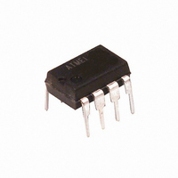
ATTINY15L-1PI Atmel, ATTINY15L-1PI Datasheet - Page 54

ATTINY15L-1PI
Manufacturer Part Number
ATTINY15L-1PI
Description
IC AVR MCU 1K FLASH 2.7V 8DIP
Manufacturer
Atmel
Series
AVR® ATtinyr
Specifications of ATTINY15L-1PI
Core Processor
AVR
Core Size
8-Bit
Speed
1.6MHz
Peripherals
Brown-out Detect/Reset, POR, PWM, WDT
Number Of I /o
6
Program Memory Size
1KB (512 x 16)
Program Memory Type
FLASH
Eeprom Size
64 x 8
Voltage - Supply (vcc/vdd)
2.7 V ~ 5.5 V
Data Converters
A/D 4x10b
Oscillator Type
Internal
Operating Temperature
-40°C ~ 85°C
Package / Case
8-DIP (0.300", 7.62mm)
Lead Free Status / RoHS Status
Contains lead / RoHS non-compliant
Ram Size
-
Connectivity
-
Available stocks
Company
Part Number
Manufacturer
Quantity
Price
Company:
Part Number:
ATTINY15L-1PI
Manufacturer:
AIMEL
Quantity:
5 510
Company:
Part Number:
ATTINY15L-1PI
Manufacturer:
VISHAY
Quantity:
5 510
Part Number:
ATTINY15L-1PI
Manufacturer:
ATMEL/爱特梅尔
Quantity:
20 000
Memory
Programming
Program and Data
Memory Lock Bits
Fuse Bits
Signature Bytes
54
ATtiny15L
The ATtiny15L MCU provides two Lock bits that can be left unprogrammed, “1”, or can
be programmed, “0”, to obtain the additional features listed in Table 23. The Lock bits
can only be erased with the Chip Erase command
Table 23. Lock Bit Protection Modes
The ATtiny15L has six Fuse bits (BODLEVEL, BODEN, SPIEN, RSTDSBL, and
CKSEL1..0). All the Fuse bits are programmable in both High-voltage and Low-voltage
Serial Programming modes. Changing the Fuses does not have effect while in program-
ming mode.
•
•
•
•
•
The status of the Fuse bits is not affected by Chip Erase.
Note:
All Atmel microcontrollers have a three-byte signature code that identifies the device.
The three bytes reside in a separate address space, and for the ATtiny15L they are:
1. $000 : $1E (indicates manufactured by Atmel).
2. $001 : $90 (indicates 1 Kb Flash memory).
3. $002 : $06 (indicates ATtiny15L device when $001 is $90).
Mode
Memory Lock Bits
1
2
3
The BODLEVEL Fuse selects the Brown-out Detection level and changes the start-
up times. See “Brown-out Detection” on page 17. See Table 5 on page 15. Default
value is programmed “0”.
When the BODEN Fuse is programed “0”, the Brown-out Detector is enabled. See
“Brown-out Detection” on page 17. Default value is unprogrammed “1”.
When the SPIEN Fuse bit is programmed “0”, Low-voltage Serial Program and Data
Downloading is enabled. Default value is programmed “0”. Unprogramming this fuse
while in the Low-voltage Serial Programming mode will disable future In-System
downloading attempts.
When the RSTDISBL Fuse is programmed “0”, the External Reset function of pin
PB5 is disabled
in the Low-voltage Serial Programming mode will disable future In-System
downloading attempts.
CKSEL1..0 Fuses: See Table 5 on page 15 for which combination of CKSEL1..0 to
use. Default value is “00”, 64 ms + 18 CK.
1. If the RSTDISBL Fuse is programmed, then the programming hardware should apply
LB1
+12V to PB5 while the ATtiny15L is in Power-on Reset. If not, the part can fail to enter
Programming mode caused by drive contention on PB0 and/or PB5.
1
0
0
LB2
1
1
0
(1)
. Default value is unprogrammed “1”. Programming this fuse while
Protection Type
No memory lock features enabled.
Further programming of the Flash and EEPROM is disabled.
Same as mode 2, but verify is also disabled.
.
1187H–AVR–09/07


