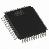
T89C51CC01UA-RLTIM Atmel, T89C51CC01UA-RLTIM Datasheet - Page 3

T89C51CC01UA-RLTIM
Manufacturer Part Number
T89C51CC01UA-RLTIM
Description
IC 8051 MCU FLASH 32K 44VQFP
Manufacturer
Atmel
Series
AT89C CANr
Datasheets
1.T89C51CC01CA-7CTIM.pdf
(167 pages)
2.T89C51CC01CA-7CTIM.pdf
(12 pages)
3.T89C51CC01CA-7CTIM.pdf
(32 pages)
4.T89C51CC01CA-7CTIM.pdf
(29 pages)
Specifications of T89C51CC01UA-RLTIM
Core Processor
8051
Core Size
8-Bit
Speed
40MHz
Connectivity
CAN, UART/USART
Peripherals
POR, PWM, WDT
Number Of I /o
32
Program Memory Size
32KB (32K x 8)
Program Memory Type
FLASH
Eeprom Size
2K x 8
Ram Size
1.25K x 8
Voltage - Supply (vcc/vdd)
3 V ~ 5.5 V
Data Converters
A/D 8x10b
Oscillator Type
External
Operating Temperature
-40°C ~ 85°C
Package / Case
44-TQFP, 44-VQFP
For Use With
AT89STK-06 - KIT DEMOBOARD 8051 MCU W/CAN
Lead Free Status / RoHS Status
Contains lead / RoHS non-compliant
Other names
T89C51CC01UARLTIM
Available stocks
Company
Part Number
Manufacturer
Quantity
Price
11. CAN – CANCONCH Harmless Corruption
12. Flash/EEPROM – First Read after Load Disturbed
13. CAN – Sporadic Errors
14. C51 Core
15. Timer0/1
4131J–CAN–05/06
Workaround
Disable all interrupts (Interrupt Global Enablet Bit) before starting an A/D conversion in idle mode, then re-enable all
interrupts immediately after.
When the stuff error occurs (same condition than the errata 6), the CONCH1, CONCH0 bits in CANCONCH are cor-
rupted. This corruption has no effect on the behavior of the Transmit channel.
Workaround
No workaround is required, re-writing CANCONCH to start a new message resolves this corruption.
In the ‘In-Application Programming’ mode from the Flash, if the User software application loads the Column Latch Area
prior to calling the programming sequence in the CAN Bootloader.
The ‘Read after load’ issue leads to a wrong Opcode Fetch during the column latch load sequence.
Workaround
Update of the Flash API Library. A NOP instruction has to be inserted after the load instruction.
When BRP = 0 or when BRP > 0 and SMP = 0, the CAN controller may desynchronize and send one error frame to ask
for the retransmission of the incoming frame, even though it had no error.
This is likely to occur with BRP = 0 or after long inter frame periods without synchronization (low bus load). The CAN
macro can still properly synchronize on frames following the error.
Workaround
Setting BRP greater than 0 in CANBT1 and SMP equals 1 in CANBT3 allows re-synchronization with the majority vote,
and thus fixes the issue.
The sampling point might have to be slightly advanced for the majority vote to take place within the bit. Therefore, at
maximum speed of 1Mbit/s, the sampling point should be at less than 80% (e.g. 75%) for XTAL = 16 MHz or less than
85% (e.g. 80%) for XTAL = 20 MHz.
When exiting power-down mode by interrupt while CPU is in X2 mode, it leads to bad execution of the first instruction
run when CPU restarts.
Workaround
Set the CPU in X1 mode diretly before entering power-down mode.
When the Timer0 is in X1 mode and Timer1 in X2 mode and vice versa, extra interrupt may randomly occured for
Timer0 or Timer1.
Workaround
Use the same mode for the two timers.
MOVX @DPTR,A ;Load Column latches
NOP ; ADDED INSTRUCTION
–
–
Extra interrupt.
Bad Exit of Power-down in X2 Mode
.
T89C51CC01 Errata Sheet
3


