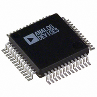
ADUC836BS Analog Devices Inc, ADUC836BS Datasheet - Page 61

ADUC836BS
Manufacturer Part Number
ADUC836BS
Description
IC ADC DUAL 16BIT W/MCU 52-MQFP
Manufacturer
Analog Devices Inc
Series
MicroConverter® ADuC8xxr
Datasheet
1.ADUC836BSZ.pdf
(80 pages)
Specifications of ADUC836BS
Rohs Status
RoHS non-compliant
Core Processor
8052
Core Size
8-Bit
Speed
12.58MHz
Connectivity
EBI/EMI, I²C, SPI, UART/USART
Peripherals
POR, PSM, PWM, Temp Sensor, WDT
Number Of I /o
34
Program Memory Size
62KB (62K x 8)
Program Memory Type
FLASH
Eeprom Size
4K x 8
Ram Size
2.25K x 8
Voltage - Supply (vcc/vdd)
2.7 V ~ 5.25 V
Data Converters
A/D 7x16b; D/A 1x12b
Oscillator Type
Internal
Operating Temperature
-40°C ~ 125°C
Package / Case
52-MQFP, 52-PQFP
Available stocks
Company
Part Number
Manufacturer
Quantity
Price
Company:
Part Number:
ADUC836BS
Manufacturer:
ADI
Quantity:
250
Part Number:
ADUC836BS
Manufacturer:
ADI/亚德诺
Quantity:
20 000
Company:
Part Number:
ADUC836BSZ
Manufacturer:
ADI
Quantity:
150
Company:
Part Number:
ADUC836BSZ
Manufacturer:
Analog Devices Inc
Quantity:
10 000
Part Number:
ADUC836BSZ
Manufacturer:
ADI/亚德诺
Quantity:
20 000
INTERRUPT SYSTEM
The ADuC836 provides a total of 11 interrupt sources with two priority levels. The control and configuration of the interrupt system
are carried out through three interrupt-related SFRs: the IE (Interrupt Enable) Register, IP (Interrupt Priority Register), and IEIP2
(Secondary Interrupt Enable/Priority SFR) Registers. Their bit definitions are given in the Tables XXXV to XXXVII.
IE
SFR Address
Power-On Default Value
Bit Addressable
Bit
7
6
5
4
3
2
1
0
IP
SFR Address
Power-On Default Value
Bit Addressable
Bit
7
6
5
4
3
2
1
0
IEIP2
SFR Address
Power-On Default Value
Bit Addressable
Bit
7
6
5
4
3
2
1
0
REV. A
Name
EA
EADC
ET2
ES
ET1
EX1
ET0
EX0
Name
–––
PADC
PT2
PS
PT1
PX1
PT0
PX0
Name
–––
PTI
PPSM
PSI
–––
ETI
EPSM
ESI
Interrupt Enable Register
A8H
00H
Yes
Interrupt Priority Register
B8H
00H
Yes
Secondary Interrupt Enable and
Priority Register
A9H
A0H
No
Description
Written by User to Enable 1 or Disable 0 All Interrupt Sources
Written by User to Enable 1 or Disable 0 ADC Interrupt
Written by User to Enable 1 or Disable 0 Timer 2 Interrupt
Written by User to Enable 1 or Disable 0 UART Serial Port Interrupt
Written by User to Enable 1 or Disable 0 Timer 1 Interrupt
Written by User to Enable 1 or Disable 0 External Interrupt 1
Written by User to Enable 1 or Disable 0 Timer 0 Interrupt
Written by User to Enable 1 or Disable 0 External Interrupt 0
Description
Reserved for Future Use
Written by User to Select ADC Interrupt Priority (1 = High; 0 = Low)
Written by User to Select Timer 2 Interrupt Priority (1 = High; 0 = Low)
Written by User to Select UART Serial Port Interrupt Priority (1 = High; 0 = Low)
Written by User to Select Timer 1 Interrupt Priority (1 = High; 0 = Low)
Written by User to Select External Interrupt 1 Priority (1 = High; 0 = Low)
Written by User to Select Timer 0 Interrupt Priority (1 = High; 0 = Low)
Written by User to Select External Interrupt 0 Priority (1 = High; 0 = Low)
Description
Reserved for Future Use
Written by User to Select TIC Interrupt Priority (1 = High; 0 = Low)
Written by User to Select Power Supply Monitor Interrupt Priority (1 = High; 0 = Low)
Written by User to Select SPI/I
Reserved. This bit must be 0.
Written by User to Enable 1 or Disable 0 TIC Interrupt
Written by User to Enable 1 or Disable 0 Power Supply Monitor Interrupt
Written by User to Enable 1 or Disable 0 SPI/I
Table XXXVII. IEIP2 SFR Bit Designations
Table XXXVI. IP SFR Bit Designations
Table XXXV. IE SFR Bit Designations
2
–61–
C Serial Port Interrupt Priority (1 = High; 0 = Low)
2
C Serial Port Interrupt
ADuC836


