P89LPC932A1FA,129 NXP Semiconductors, P89LPC932A1FA,129 Datasheet - Page 32
P89LPC932A1FA,129
Manufacturer Part Number
P89LPC932A1FA,129
Description
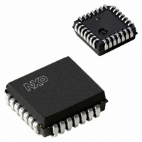
IC 80C51 MCU FLASH 8K 28-PLCC
Manufacturer
NXP Semiconductors
Series
LPC900r
Datasheet
1.P89LPC932A1FDH529.pdf
(64 pages)
Specifications of P89LPC932A1FA,129
Core Processor
8051
Core Size
8-Bit
Speed
18MHz
Connectivity
I²C, SPI, UART/USART
Peripherals
Brown-out Detect/Reset, LED, POR, PWM, WDT
Number Of I /o
26
Program Memory Size
8KB (8K x 8)
Program Memory Type
FLASH
Ram Size
768 x 8
Voltage - Supply (vcc/vdd)
2.4 V ~ 3.6 V
Oscillator Type
Internal
Operating Temperature
-40°C ~ 85°C
Package / Case
28-PLCC
For Use With
OM6292 - DEMO BOARD PCA2125 RTCDB-TSSOP-LPC932 - BOARD FOR LPC932 TSSOP622-1014 - BOARD FOR LPC9XX TSSOP622-1008 - BOARD FOR LPC9103 10-HVSON622-1006 - SOCKET ADAPTER BOARDMCB900K - BOARD PROTOTYPE NXP 89LPC9EPM900K - EMULATOR/PROGRAMMER NXP P89LPC9622-1003 - KIT FOR LCD DEMO568-1759 - EMULATOR DEBUGGER/PROGRMMR LPC9X568-1758 - BOARD EVAL FOR LPC93X MCU FAMILY
Lead Free Status / RoHS Status
Lead free / RoHS Compliant
Eeprom Size
-
Data Converters
-
Other names
568-1285-5
935276131129
P89LPC932A1FA-S
935276131129
P89LPC932A1FA-S
Available stocks
Company
Part Number
Manufacturer
Quantity
Price
Company:

Part Number:
P89LPC932A1FA,129
Manufacturer:
NXP Semiconductors
Quantity:
10 000


NXP Semiconductors
P89LPC932A1_3
Product data sheet
7.20.10 The 9
7.20.8 Double buffering
7.20.9 Transmit interrupts with double buffering enabled (modes 1, 2 and 3)
The UART has a transmit double buffer that allows buffering of the next character to be
written to SBUF while the first character is being transmitted. Double buffering allows
transmission of a string of characters with only one stop bit between any two characters,
as long as the next character is written between the start bit and the stop bit of the
previous character.
Double buffering can be disabled. If disabled (DBMOD, i.e., SSTAT.7 = 0), the UART is
compatible with the conventional 80C51 UART. If enabled, the UART allows writing to
SnBUF while the previous data is being shifted out. Double buffering is only allowed in
Modes 1, 2 and 3. When operated in Mode 0, double buffering must be disabled
(DBMOD = 0).
Unlike the conventional UART, in double buffering mode, the Tx interrupt is generated
when the double buffer is ready to receive new data.
If double buffering is disabled TB8 can be written before or after SBUF is written, as long
as TB8 is updated some time before that bit is shifted out. TB8 must not be changed until
the bit is shifted out, as indicated by the Tx interrupt.
If double buffering is enabled, TB8 must be updated before SBUF is written, as TB8 will
be double-buffered together with SBUF data.
th
bit (bit 8) in double buffering (modes 1, 2 and 3)
Rev. 03 — 12 March 2007
8-bit microcontroller with accelerated two-clock 80C51 core
P89LPC932A1
© NXP B.V. 2007. All rights reserved.
32 of 64
Related parts for P89LPC932A1FA,129
Image
Part Number
Description
Manufacturer
Datasheet
Request
R

Part Number:
Description:
P89lpc932 8-bit Microcontroller With Accelerated Two-clock 80c51 Core 8 Kb Flash With 512-byte Data Eeprom And 768-byte Ram
Manufacturer:
NXP Semiconductors
Datasheet:
Part Number:
Description:
NXP Semiconductors designed the LPC2420/2460 microcontroller around a 16-bit/32-bitARM7TDMI-S CPU core with real-time debug interfaces that include both JTAG andembedded trace
Manufacturer:
NXP Semiconductors
Datasheet:

Part Number:
Description:
NXP Semiconductors designed the LPC2458 microcontroller around a 16-bit/32-bitARM7TDMI-S CPU core with real-time debug interfaces that include both JTAG andembedded trace
Manufacturer:
NXP Semiconductors
Datasheet:
Part Number:
Description:
NXP Semiconductors designed the LPC2468 microcontroller around a 16-bit/32-bitARM7TDMI-S CPU core with real-time debug interfaces that include both JTAG andembedded trace
Manufacturer:
NXP Semiconductors
Datasheet:
Part Number:
Description:
NXP Semiconductors designed the LPC2470 microcontroller, powered by theARM7TDMI-S core, to be a highly integrated microcontroller for a wide range ofapplications that require advanced communications and high quality graphic displays
Manufacturer:
NXP Semiconductors
Datasheet:
Part Number:
Description:
NXP Semiconductors designed the LPC2478 microcontroller, powered by theARM7TDMI-S core, to be a highly integrated microcontroller for a wide range ofapplications that require advanced communications and high quality graphic displays
Manufacturer:
NXP Semiconductors
Datasheet:
Part Number:
Description:
The Philips Semiconductors XA (eXtended Architecture) family of 16-bit single-chip microcontrollers is powerful enough to easily handle the requirements of high performance embedded applications, yet inexpensive enough to compete in the market for hi
Manufacturer:
NXP Semiconductors
Datasheet:
Part Number:
Description:
The XA-S3 device is a member of Philips Semiconductors? XA(eXtended Architecture) family of high performance 16-bitsingle-chip microcontrollers
Manufacturer:
NXP Semiconductors
Datasheet:

Part Number:
Description:
The NXP BlueStreak LH75401/LH75411 family consists of two low-cost 16/32-bit System-on-Chip (SoC) devices
Manufacturer:
NXP Semiconductors
Datasheet:
Part Number:
Description:
The NXP LPC3130/3131 combine an 180 MHz ARM926EJ-S CPU core, high-speed USB2
Manufacturer:
NXP Semiconductors
Datasheet:
Part Number:
Description:
The NXP LPC3141 combine a 270 MHz ARM926EJ-S CPU core, High-speed USB 2
Manufacturer:
NXP Semiconductors
Part Number:
Description:
The NXP LPC3143 combine a 270 MHz ARM926EJ-S CPU core, High-speed USB 2
Manufacturer:
NXP Semiconductors

Part Number:
Description:
The NXP LPC3152 combines an 180 MHz ARM926EJ-S CPU core, High-speed USB 2
Manufacturer:
NXP Semiconductors
Part Number:
Description:
The NXP LPC3154 combines an 180 MHz ARM926EJ-S CPU core, High-speed USB 2
Manufacturer:
NXP Semiconductors