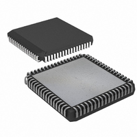
DS87C550-QNL Maxim Integrated Products, DS87C550-QNL Datasheet - Page 8

DS87C550-QNL
Manufacturer Part Number
DS87C550-QNL
Description
IC MCU EPROM ADC/PWM HS 68-PLCC
Manufacturer
Maxim Integrated Products
Series
87Cr
Datasheet
1.DS87C550-QNL.pdf
(49 pages)
Specifications of DS87C550-QNL
Core Processor
8051
Core Size
8-Bit
Speed
33MHz
Connectivity
EBI/EMI, SIO, UART/USART
Peripherals
Power-Fail Reset, PWM, WDT
Number Of I /o
55
Program Memory Size
8KB (8K x 8)
Program Memory Type
OTP
Ram Size
1K x 8
Voltage - Supply (vcc/vdd)
4.5 V ~ 5.5 V
Data Converters
A/D 6x10b
Oscillator Type
External
Operating Temperature
-40°C ~ 85°C
Package / Case
68-LCC, 68-PLCC
Lead Free Status / RoHS Status
Contains lead / RoHS non-compliant
Eeprom Size
-
Available stocks
Company
Part Number
Manufacturer
Quantity
Price
Company:
Part Number:
DS87C550-QNL
Manufacturer:
Maxim Integrated
Quantity:
10 000
Part Number:
DS87C550-QNL
Manufacturer:
DALLAS
Quantity:
20 000
instruction used two machine cycles or 24 oscillator cycles. Therefore, they required the same amount of
time. In the DS87C550, the MOVX instruction takes as little as two machine cycles or eight oscillator
cycles, but the “MOV direct, direct” uses three machine cycles or 12 oscillator cycles. While both are
faster than their original counterparts, they now have different execution times. This is because the
DS87C550 usually uses one instruction cycle for each instruction byte. Examine the timing of each
instruction for familiarity with the changes. Note that a machine cycle now requires just 4 clocks, and
provides one ALE pulse per cycle. Many instructions require only one cycle, but some require five. In the
original architecture, all were one or two cycles except for MUL and DIV. Refer to the High Speed Micro
User’s Guide for details and individual instruction timing.
SPECIAL FUNCTION REGISTERS
Special Function Registers (SFRs) control most special features of the DS87C550. This allows the
DS87C550 to have many new features but use the same instruction set as the 8051. When writing
software to use a new feature, an equate statement defines the SFR to an assembler or compiler. This is
the only change needed to access the new function. The DS87C550 duplicates the SFRs contained in the
standard 80C52. Table 2 shows the register addresses and bit locations. Many are standard 80C52
registers. The High Speed Micro User’s Guide describes all SFRs in full detail.
SPECIAL FUNCTION REGISTER LOCATION: Table 2
ADCON1
REGISTER
SADDR0
SADDR1
CKCON
SCON0
CMPL0
CMPL1
CMPL2
PORT0
PORT1
PORT2
PORT3
TMOD
SBUF0
CPTL0
CPTL1
CPTL2
CPTL3
TCON
RCON
PCON
DPH1
DPL1
PMR
DPH
DPL
DPS
TH0
TH1
TL0
TL1
SP
IE
SM0/FE_0
SMOD_0
STRT/BSY
GATE
WD1
P0.7
P1.7
CD1
P2.7
P3.7
BIT7
TF1
ID1
EA
-
SMOD0
SM1_0
WD0
EAD
CD0
EOC
P0.6
TR1
C/
P1.6
P2.6
P3.6
BIT6
ID0
-
T
CONT/SS
SM2_0
OFDF
SWB
T2M
P0.5
TSL
P1.5
P2.5
P3.5
BIT5
TF0
ES1
M1
-
REN_0
ADEX
OFDE
CTM
T1M
P0.4
P1.4
TR0
P2.4
P3.4
BIT4
ES0
8 of 49
M0
-
-
CKRDY
4X/
TB8_0
GATE
WCQ
T0M
P0.3
P1.3
P2.3
P3.3
GF1
ET1
BIT3
IE1
-
2X
ALEOFF
RGMD
RB8_0
WCM
MD2
P0.2
C/
P1.2
P2.2
EX1
P3.2
GF0
BIT2
IT1
-
T
ADON
DEM1
STOP
RGSL
MD1
TI_0
P0.1
P1.1
P2.1
P3.1
BIT1
ET0
IE0
M1
-
DME0
WCIO
IDLE
MD0
RI_0
BGS
P0.0
P1.0
P2.0
EX0
P3.0
BIT0
SEL
IT0
M0
ADDRESS
AAh
ADh
ABh
ACh
AEh
8Ah
8Dh
A0h
A1h
A2h
A8h
A9h
AFh
8Bh
8Ch
8Eh
B0h
B2h
80h
81h
82h
83h
84h
85h
86h
87h
88h
89h
90h
91h
98h
99h
9Fh


