MCP6V06T-E/MNY Microchip Technology, MCP6V06T-E/MNY Datasheet - Page 28
MCP6V06T-E/MNY
Manufacturer Part Number
MCP6V06T-E/MNY
Description
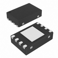
IC OPAMP AUTO-ZERO SGL 8-TDFN
Manufacturer
Microchip Technology
Datasheet
1.MCP6V06T-EMNY.pdf
(44 pages)
Specifications of MCP6V06T-E/MNY
Slew Rate
0.5 V/µs
Amplifier Type
Chopper (Zero-Drift)
Number Of Circuits
1
Output Type
Rail-to-Rail
Gain Bandwidth Product
1.3MHz
Current - Input Bias
6pA
Voltage - Input Offset
3µV
Current - Supply
300µA
Current - Output / Channel
22mA
Voltage - Supply, Single/dual (±)
1.8 V ~ 5.5 V
Operating Temperature
-40°C ~ 125°C
Mounting Type
Surface Mount
Package / Case
8-TDFN
Op Amp Type
Precision
No. Of Amplifiers
1
Bandwidth
1.3MHz
Supply Voltage Range
1.8V To 5.5V
Amplifier Case Style
TQFN
No. Of Pins
8
Number Of Channels
1
Voltage Gain Db
158 dB
Common Mode Rejection Ratio (min)
120 dB
Input Offset Voltage
0.003 mV
Operating Supply Voltage
3 V, 5 V
Maximum Operating Temperature
+ 125 C
Mounting Style
SMD/SMT
Minimum Operating Temperature
- 40 C
Lead Free Status / RoHS Status
Lead free / RoHS Compliant
-3db Bandwidth
-
Lead Free Status / Rohs Status
Details
Other names
MCP6V06T-E/MNYTR
Available stocks
Company
Part Number
Manufacturer
Quantity
Price
Company:

Part Number:
MCP6V06T-E/MNY
Manufacturer:
Microchip Technology
Quantity:
135
Company:
Part Number:
MCP6V06T-E/MNY
Manufacturer:
MICROCHIP
Quantity:
12 000


MCP6V06/7/8
4.3.9.5
In cases where an individual resistor needs to have its
thermo-junction voltage cancelled, it can be split into
two equal resistors as shown in
the thermal gradients near the resistors as small as
possible, the layouts are symmetrical with a ring of
metal around the outside. Make R
R
FIGURE 4-14:
Resistors.
Minimize temperature gradients at critical components
(resistors, op amps, heat sources, etc.):
• Minimize exposure to gradients
• Align with constant temperature (contour) lines
• Minimize magnitude of gradients
Make the temperature gradient point in one direction:
• Add guard traces
• Shape any FR4 gaps
DS22093B-page 28
2A
Note:
- Small components
- Tight spacing
- Shield from air currents
- Place on PCB center line
- Select parts with lower power dissipation
- Use same metal junctions on thermo-junc-
- Use metal junctions with low temperature to
- Large distance from heat sources
- Ground plane underneath (large area)
- FR4 gaps (no copper for thermal insulation)
- Series resistors inserted into traces (adds
- Use heat sinks
- Constant temperature curves follow the
- Connect to ground plane
- Constant temperature curves follow the
= R
tions that need to match
voltage coefficients
thermal and electrical resistance)
traces
edges
R
2B
1A
R
= 2R
1A
Changing the orientation of the resistors
will usually cause a significant decrease in
the cancellation of the thermal voltages.
Other PCB Thermal Design Tips
R
2
.
1B
R
1B
PCB Layout for Individual
Figure
1A
R
R
= R
2A
2B
R
R
2A
2B
4-14. To keep
1B
= R
1
/2 and
4.3.9.6
DC crosstalk causes offsets that appear as a larger
input offset voltage. Common causes include:
• Common mode noise (remote sensors)
• Ground loops (current return paths)
• Power supply coupling
Interference from the mains (usually 50 Hz or 60 Hz),
and other AC sources, can also affect the DC perfor-
mance. Non-linear distortion can convert these signals
to multiple tones, included a DC shift in voltage. When
the signal is sampled by an ADC, these AC signals can
also be aliased to DC, causing an apparent shift in
offset.
To reduce interference:
4.3.9.7
Keep the resistances seen by the input pins as small
and as near to equal as possible to minimize bias cur-
rent related offsets.
Make the (trace) capacitances seen by the input pins
small and equal. This is helpful in minimizing switching
glitch-induced offset voltages.
Bending a coax cable with a radius that is too small
causes a small voltage drop to appear on the center or
(the tribo-electric effect). Make sure the bending radius
is large enough to keep the conductors and insulation
in full contact.
Mechanical stresses can make some capacitor types
(such as ceramic) to output small voltages. Use more
appropriate capacitor types in the signal path and
minimize mechanical stresses and vibration.
Humidity can cause electro-chemical potential voltages
to appear in a circuit. Proper PCB cleaning helps, as
does the use of encapsulants.
- Keep traces and wires as short as possible
- Use shielding (e.g., encapsulant)
- Use ground plane (at least a star ground)
- Place the input signal source near to the DUT
- Use good PCB layout techniques
- Use a separate power supply filter (bypass
capacitors) for these auto-zeroed op amps
Crosstalk
Miscellaneous Effects
© 2008 Microchip Technology Inc.
Related parts for MCP6V06T-E/MNY
Image
Part Number
Description
Manufacturer
Datasheet
Request
R

Part Number:
Description:
Single, Auto-Zero Op Amp, E Temp 8 SOIC 3.90mm (.150") T/R
Manufacturer:
Microchip Technology
Datasheet:
Part Number:
Description:
Operational Amplifiers - Op Amps SNGL Auto-Zero Op Amp E Temp
Manufacturer:
Microchip Technology

Part Number:
Description:
Manufacturer:
Microchip Technology Inc.
Datasheet:
Part Number:
Description:
Manufacturer:
Microchip Technology Inc.
Datasheet:
Part Number:
Description:
Manufacturer:
Microchip Technology Inc.
Datasheet:
Part Number:
Description:
Manufacturer:
Microchip Technology Inc.
Datasheet:
Part Number:
Description:
Manufacturer:
Microchip Technology Inc.
Datasheet:
Part Number:
Description:
Manufacturer:
Microchip Technology Inc.
Datasheet:
Part Number:
Description:
Manufacturer:
Microchip Technology Inc.
Datasheet:
Part Number:
Description:
Manufacturer:
Microchip Technology Inc.
Datasheet: