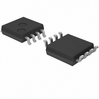
BU7442SFVM-TR Rohm Semiconductor, BU7442SFVM-TR Datasheet - Page 27

BU7442SFVM-TR
Manufacturer Part Number
BU7442SFVM-TR
Description
IC OPAMP 1.7-5.5V GRD SENS 8MSOP
Manufacturer
Rohm Semiconductor
Datasheet
1.BU7461G-TR.pdf
(37 pages)
Specifications of BU7442SFVM-TR
Amplifier Type
General Purpose
Number Of Circuits
2
Slew Rate
0.3 V/µs
Gain Bandwidth Product
600kHz
Current - Input Bias
1pA
Voltage - Input Offset
1000µV
Current - Supply
100µA
Current - Output / Channel
10mA
Voltage - Supply, Single/dual (±)
1.7 V ~ 5.5 V
Operating Temperature
-40°C ~ 105°C
Mounting Type
Surface Mount
Package / Case
8-MSOP, Micro8™, 8-uMAX, 8-uSOP,
Number Of Channels
2
Common Mode Rejection Ratio (min)
45 dB
Input Offset Voltage
6 mV
Input Bias Current (max)
1 pA
Output Current (typ)
6 mA, 10 mA
Operating Supply Voltage
1.7 V to 5.5 V
Supply Current
0.24 mA
Maximum Power Dissipation
480 mW
Maximum Operating Temperature
+ 105 C
Minimum Operating Temperature
- 40 C
Maximum Dual Supply Voltage
+/- 2.75 V
Minimum Dual Supply Voltage
+/- 0.85 V
Mounting Style
SMD/SMT
Shutdown
No
Supply Voltage (max)
5.5 V
Supply Voltage (min)
1.7 V
Technology
CMOS
Voltage Gain Db
95 dB
Lead Free Status / RoHS Status
Lead free / RoHS Compliant
Output Type
-
-3db Bandwidth
-
Lead Free Status / Rohs Status
Lead free / RoHS Compliant
Available stocks
Company
Part Number
Manufacturer
Quantity
Price
Company:
Part Number:
BU7442SFVM-TR
Manufacturer:
Rohm
Quantity:
5 186
BU7261/BU7261S family, BU7241/BU7241S family, BU7295/BU7295S family, BU7275/BU7275S family
BU7262/BU7262S family, BU7242/BU7242S family, BU7264/BU7264S family, BU7244/BU7244S family
●Test circuit 1 NULL method
© 2010 ROHM Co., Ltd. All rights reserved.
www.rohm.com
Input Offset Voltage
Large Signal Voltage Gain
Common-mode Rejection Ratio
(Input Common-mode Voltage Range)
Power Supply Rejection Ratio
-Calculation-
1. Input Offset Voltage (Vio)
2. Large Signal Voltage Gain (Av)
3. Common-mode Rejection Ratio (CMRR)
4. Power Supply Rejection Ratio (PSRR)
Parameter
Vicm
RS=50[ Ω ]
RS=50[ Ω ]
50[k Ω ]
0.015[µF]
Ri=1[M Ω ]
Ri=1[M Ω ]
SW2
SW1
0.015[µF]
Fig.185 Test circuit 1 (one channel only)
VF1
VF2
VF3
VF4
VF5
VF6
VF7
VF
VDD
VSS
DUT
CMRR
PSRR
Vio
Av
ON
ON
ON
ON
S1
=
=
VRL
SW3
20Log
RL
=
=
1+Rf/Rs
20Log
Vo
|VF1|
27/36
20Log
ON
ON
ON
ON
S2
Rf=50[k Ω ]
0.1[µF]
2×(1+Rf/Rs)
|VF2-VF3|
EK
3.7×(1+Rf/Rs)
1.8×(1+Rf/Rs)
1000[pF]
[V]
500[k Ω ]
|VF4-VF5|
|VF6-VF7|
OFF
OFF
OFF
ON
S3
500[k Ω ]
[dB]
VDD
1.8
5.5
3
3
3
[dB]
[dB]
LL
-15[V]
15[V]
VSS
0.01[µF]
0
0
0
0
VDD, VSS, EK, Vicm Unit: [V]
-1.5
-0.5
-2.5
-1.5
-0.9
EK
VF
Technical Note
2010.12 - Rev.A
Vicm
1.5
3
0
3
0
Calculation
1
2
3
4


