AD549LHZ Analog Devices Inc, AD549LHZ Datasheet - Page 16
AD549LHZ
Manufacturer Part Number
AD549LHZ
Description
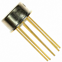
IC OPAMP GP 1MHZ LP 20MA TO99-8
Manufacturer
Analog Devices Inc
Series
Topgate™r
Datasheet
1.AD549JHZ.pdf
(20 pages)
Specifications of AD549LHZ
Slew Rate
3 V/µs
Amplifier Type
General Purpose
Number Of Circuits
1
Gain Bandwidth Product
1MHz
Current - Input Bias
0.04pA
Voltage - Input Offset
300µV
Current - Supply
600µA
Current - Output / Channel
20mA
Voltage - Supply, Single/dual (±)
±5 V ~ 18 V
Operating Temperature
0°C ~ 70°C
Mounting Type
Through Hole
Package / Case
TO-99-8, Metal Can
Op Amp Type
Low Bias Current
No. Of Amplifiers
1
Bandwidth
1MHz
Supply Voltage Range
± 5V To ± 18V
Amplifier Case Style
TO-99
No. Of Pins
8
Lead Free Status / RoHS Status
Lead free / RoHS Compliant
Output Type
-
-3db Bandwidth
-
Lead Free Status / Rohs Status
RoHS Compliant part
Electrostatic Device
Available stocks
Company
Part Number
Manufacturer
Quantity
Price

Part Number:
AD549LHZ
Manufacturer:
ADI/亚德诺
Quantity:
20 000


AD549
Frequency compensation is provided by R11, R12, C1, and C2.
The bandwidth of the circuit is 300 kHz at input signals greater
than 50 μA; bandwidth decreases smoothly with decreasing
signal levels.
To trim the circuit, set the input currents to 10 μA and trim the
A3 offset using the trim potentiometer of the amplifier for the
output to equal 0. Next, set I
equal 1 V by trimming R10. Additional offset trims on Ampli-
fier A1 and Amplifier A2 can be used to increase the voltage
input accuracy and dynamic range.
The very low input current of the AD549 makes this circuit
useful over a very wide range of signal currents. The total input
current (which determines the low level accuracy of the circuit)
is the sum of the amplifier input current, the leakage across the
compensating capacitor (negligible if a polystyrene or Teflon
capacitor is used), and the collector-to-collector and collector-
to-base leakages of one side of the dual log transistors. The
magnitudes of these last two leakages depend on the amplifier
input offset voltage and are typically less than 10 fA with 1 mV
offsets. The low level accuracy is limited primarily by the
amplifier input current, only 60 fA maximum when the
AD549L is used.
The effects of the emitter resistance of Q1 and Q2 can degrade
circuit accuracy at input currents above 100 μA. The networks
1
to 1 μA and adjust the output to
V
V
I
I
1
1
2
2
IN
IN
IN
IN
10kΩ
10kΩ
R1
R2
49.9kΩ
3
2
2
3
R14
100pF
100pF
D2
AD549
AD549
C1
C2
4
4
A1
A2
Q1
1
Q2
1
R16
10Ω
R17
10Ω
10kΩ
A
B
5
5
V
OFFSET
V
OFFSET
10kΩ
2
Figure 45. Log Ratio Amplifier
1
6
6
Rev. H | Page 16 of 20
R13
49.9kΩ
D1
20kΩ
R11
4.99kΩ
4.99kΩ
R3
20kΩ
D3
D4
FOR EACH AMPLIFIER
R4
D1, D4 1N4148 DIODES
R8, R15 1kΩ + 350 ppm/°C TC RESISTOR
*
ALL OTHER RESISTORS ARE 1% METAL FILM
TELLAB QB1 OR PRECISION RESISTOR PT146
PIN 7
PIN 4
Q1, Q2 = LM394
DUAL LOG TRANSISTORS
3
2
20kΩ
composed of R13, D1, R16, R14, D2, and R17 compensate for
these errors, so that this circuit has less than a 1% log confor-
mance error at 1 mA input currents. The correct value for R13
and R14 depends on the type of log transistors used. The 49.9 kΩ
resistors were chosen for use with LM394 transistors. Smaller
resistance values are needed for smaller log transistors.
TEMPERATURE COMPENSATED pH PROBE
AMPLIFIER
A pH probe can be modeled as an mV-level voltage source
with a series source resistance dependent on the electrode
composition and configuration. The glass bulb resistance of a
typical pH electrode pair falls between 10
therefore important to select an amplifier with low enough
input currents such that the voltage drop produced by the
amplifier input bias current and the electrode resistance does
not become an appreciable percentage of a pH unit.
The circuit in Figure 46 illustrates the use of the AD549 as a pH
probe amplifier. As with other electrometer applications, the use of
guarding, shielding, and Teflon standoffs is necessary to capitalize
on the AD549 low input current. If an AD549L (60 fA maximum
input current) is used, the error contributed by the input current is
held below 60 μV for pH electrode source impedances up to 10
Input offset voltages (which can be trimmed) are below 0.5 mV.
20kΩ
AD549
R6
R5
4
A3
1
*
R8
1kΩ
5
OUTPUT
OFFSET
10kΩ
15kΩ
R15
1kΩ
R7
6
0.1µF
0.1µF
14.3kΩ
V
V
OUT
OUT
*
R9
2kΩ
R10
= 1V × LOG
= 1V × LOG
+V
–V
V
S
S
OUT
SCALE
FACTOR
ADJ
10
10
V
V
I
I
2
1
2
1
6
Ω and 10
9
Ω. It is
9
Ω.
Related parts for AD549LHZ
Image
Part Number
Description
Manufacturer
Datasheet
Request
R

Part Number:
Description:
±1.7g Dual-Axis IMEMS Accelerometer Evaluation Board
Manufacturer:
Analog Devices Inc
Datasheet:

Part Number:
Description:
Inertial Sensor Evaluation System
Manufacturer:
Analog Devices Inc
Datasheet:
Part Number:
Description:
Manufacturer:
Analog Devices Inc
Datasheet:
Part Number:
Description:
Manufacturer:
Analog Devices Inc
Datasheet:
Part Number:
Description:
Manufacturer:
Analog Devices Inc
Datasheet:
Part Number:
Description:
Manufacturer:
Analog Devices Inc
Datasheet:
Part Number:
Description:
Manufacturer:
Analog Devices Inc
Datasheet:
Part Number:
Description:
Manufacturer:
Analog Devices Inc
Datasheet:
Part Number:
Description:
Manufacturer:
Analog Devices Inc
Datasheet:
Part Number:
Description:
Manufacturer:
Analog Devices Inc
Datasheet:
Part Number:
Description:
Manufacturer:
Analog Devices Inc
Datasheet:
Part Number:
Description:
Manufacturer:
Analog Devices Inc
Datasheet:
Part Number:
Description:
Manufacturer:
Analog Devices Inc
Datasheet: