PA78EU Cirrus Logic Inc, PA78EU Datasheet - Page 5
PA78EU
Manufacturer Part Number
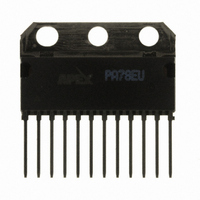
PA78EU
Description
IC PWR AMP 350V 200MA 12SIP
Manufacturer
Cirrus Logic Inc
Series
Apex Precision Power™r
Specifications of PA78EU
Amplifier Type
Power
Number Of Circuits
1
Slew Rate
350 V/µs
Gain Bandwidth Product
1MHz
Current - Input Bias
8.5pA
Voltage - Input Offset
8000µV
Current - Supply
700µA
Current - Output / Channel
150mA
Voltage - Supply, Single/dual (±)
20 V ~ 350 V, ±10 V ~ 175 V
Operating Temperature
-40°C ~ 125°C
Mounting Type
Through Hole
Package / Case
12-SIP
For Use With
598-1398 - KIT EVALUATION PA78/PA79598-1395 - EVALUATION KIT FOR PA78
Lead Free Status / RoHS Status
Lead free / RoHS Compliant
Output Type
-
-3db Bandwidth
-
Other names
598-1440
PA78EU
PA78EU
Available stocks
Company
Part Number
Manufacturer
Quantity
Price

Part Number:
PA78EU
Manufacturer:
APEX
Quantity:
20 000


III. DRIvING DEFLECTION PLATES
Drop' printing applications. In this circuit the PA78 power op-
erational amplifier connects directly to the deflection plates.
microns in diameter, are emitted by the ink source at a high
velocity and are then passed through the electrostatically-
charged region between a pair of deflection plates. Each droplet
is thereby deflected, as required to form the ink characters
deposited on the printed surface.
at the DAC (digital-to-analog converter) and is converted into
a sequence of square waves of differing voltages ranging
from zero to 3V. This wave train sequence is then fed to a
fast operational amplifier, such as the Analog Devices AD817
shown in Figure 5. The output of this device, in turn, drives
the Apex PA78 power operational amplifier.
as a sequence of square waves, differing in magnitude and
varying between zero and 300V at a repetition rate of 100
kHz. At the beginning of each programmed voltage value, the
square wave must reach its programmed voltage within 1.5
microseconds. This is essential because the programmed volt-
age must remain constant throughout the final 8.5 milliseconds,
for that is the time span for the next droplet to pass through
the deflection-plate field.
as detailed earlier, the PA78 is able to fulfill the objectives of
the design. By driving the PA78 hard, the full bandwidth of the
PA78 is realized. That is, it can be driven at a pulse repetition
rate of 100,000 — or 100 kHz — swinging between zero and
300V, within the rise-time required.
Figure 6. Enhanced Slew Rate Circuit – By driving the AD817 from the false summing node (Node B), a slew rate of 350 volts/μs
is sustained to within 1 volt of the targeted programming voltage.
APEX MICROTECHNOLOGY CORPORATION • TELEPHONE (520) 690-8600 • FAX (520) 888-3329 • ORDERS (520) 690-8601 • EMAIL prodlit@apexmicrotech.com
The circuit shown in Figure 5 was developed for 'Continuous
Electrostatically-charged ink droplets, typically 50 to 60
The programming information arrives as a digital data stream
The output of the PA78 is applied to the deflection plates,
Because of its ability to achieve extraordinary high slew rates,
a voltage gain of approximately 4V. The Apex PA78 power
operational amplifier is programmed to exhibit a gain of ap-
proximately 25. Therefore the overall gain from DAC output
to PA78 output, is approximately 100V.
output of the PA78 to swing all the way to ground.
ponents:
circuit resistor R
so that the gain of the PA78 approaches a very high value,
thereby assuring a very fast slew rate.
employed to assure stability and are discussed in more detail
in the PA78 data sheet. In general the smaller they are, the
faster the output can swing.
fectively at 100 kHz, it is essential that the parallel combina-
tion of R
R
while realizing the programmed gain of approximately 25 that
is necessary to drive the PA78.
confines the output current to a maximum of 60mA. Though
the deflection plates draw no current, the 60mA capability
can accommodate any distributed capacitance in the wiring
connecting the circuit with the deflection plates. See the PA78
data sheet for further discussion.
4
As depicted in Figure 5, the AN817 is programmed to provide
Setting –V
What follows is a discussion of the principal passive com-
C
C
R
R
, 1 kilohm and 25 kilohms, respectively, meet this criterion
1
2
3
6
— The role of this 100pF capacitor is to effectively short-
— This current limiting resistor, with a value of 12 ohms,
and R
and C
3
and R
4
3
S
— To make sure that the PA78 can operate ef-
— These are 1pF compensation capacitors
(-V
4
3
be less than 1 kilohm. The values of R
CC
during the rise and fall of the square wave
) to -15V enables both the input and the
3
and
5
Related parts for PA78EU
Image
Part Number
Description
Manufacturer
Datasheet
Request
R

Part Number:
Description:
Development Kit
Manufacturer:
Cirrus Logic Inc
Datasheet:
Part Number:
Description:
Development Kit
Manufacturer:
Cirrus Logic Inc
Datasheet:


Part Number:
Description:
High-efficiency PFC + Fluorescent Lamp Driver Reference Design
Manufacturer:
Cirrus Logic Inc
Datasheet:
Part Number:
Description:
Development Kit
Manufacturer:
Cirrus Logic Inc
Datasheet:
Part Number:
Description:
Development Kit
Manufacturer:
Cirrus Logic Inc
Datasheet:

Part Number:
Description:
Development Kit
Manufacturer:
Cirrus Logic Inc
Datasheet:
Part Number:
Description:
Development Kit
Manufacturer:
Cirrus Logic Inc
Datasheet:
Part Number:
Description:
Development Kit
Manufacturer:
Cirrus Logic Inc
Datasheet:
Part Number:
Description:
Development Kit
Manufacturer:
Cirrus Logic Inc
Datasheet:

Part Number:
Description:
EVALUATION BOARD FOR CS8427
Manufacturer:
Cirrus Logic Inc
Datasheet:

Part Number:
Description:
BOARD EVAL FOR CS8416 RCVR
Manufacturer:
Cirrus Logic Inc
Datasheet:

Part Number:
Description:
EVALUATION BOARD FOR CS8420
Manufacturer:
Cirrus Logic Inc
Datasheet:

Part Number:
Description:
KIT DEVELOPMENT EP9315 ARM9
Manufacturer:
Cirrus Logic Inc
Datasheet:

Part Number:
Description:
KIT DEVELOPMENT EP9302 ARM9
Manufacturer:
Cirrus Logic Inc
Datasheet: